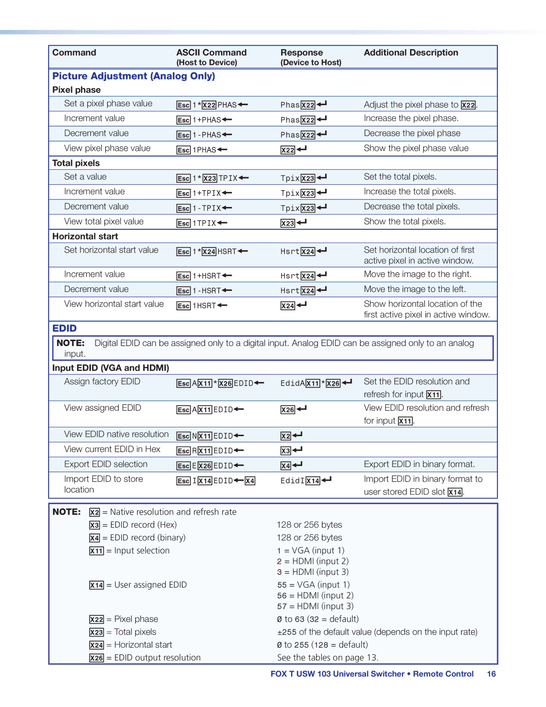
Command | ASCII Command | Response | Additional Description |
| (Host to Device) | (Device to Host) |
|
Picture Adjustment (Analog Only)
Pixel phase
Set a pixel phase value | E1*X2@PHAS} | PhasX2@] | Adjust the pixel phase to X2@. |
|
|
|
|
Increment value | E1+PHAS} | PhasX2@] | Increase the pixel phase. |
|
|
|
|
Decrement value | PhasX2@] | Decrease the pixel phase | |
|
|
|
|
View pixel phase value | E1PHAS} | X2@] | Show the pixel phase value |
Total pixels |
|
|
|
|
|
|
|
Set a value | E1*X2#TPIX} | TpixX2#] | Set the total pixels. |
|
|
|
|
Increment value | E1+TPIX} | TpixX2#] | Increase the total pixels. |
|
|
|
|
Decrement value | TpixX2#] | Decrease the total pixels. | |
|
|
|
|
View total pixel value | E1TPIX} | X2#] | Show the total pixels. |
|
|
|
|
Horizontal start |
|
|
|
|
|
|
|
Set horizontal start value | E1*X2$HSRT} | HsrtX2$] | Set horizontal location of first |
|
|
| active pixel in active window. |
Increment value | E1+HSRT} | HsrtX2$] | Move the image to the right. |
|
|
|
|
Decrement value | HsrtX2$] | Move the image to the left. | |
|
|
|
|
View horizontal start value | E1HSRT} | X2$] | Show horizontal location of the |
|
|
| first active pixel in active window. |
EDID |
|
|
|
NOTE: Digital EDID can be assigned only to a digital input. Analog EDID can be assigned only to an analog input.
Input EDID (VGA and HDMI)
Assign factory EDID | EAX1!*X2^EDID} | EdidAX1!*X2^] | Set the EDID resolution and |
|
|
| refresh for input X1!. |
View assigned EDID | EAX1!EDID} | X2^] | View EDID resolution and refresh |
|
|
| for input X1!. |
|
|
|
|
View EDID native resolution | ENX1!EDID} | X@] |
|
|
|
|
|
View current EDID in Hex | ERX1!EDID} | X#] |
|
|
|
|
|
Export EDID selection | EEX2^EDID} | X$] | Export EDID in binary format. |
|
|
|
|
Import EDID to store | EIX1$EDID}X$ | EdidIX1$] | Import EDID in binary format to |
location |
|
| user stored EDID slot X1$. |
NOTE: X@ = Native resolution and refresh rate |
|
X# = EDID record (Hex) | 128 or 256 bytes |
X$ = EDID record (binary) | 128 or 256 bytes |
X1! = Input selection | 1 = VGA (input 1) |
| 2 = HDMI (input 2) |
| 3 = HDMI (input 3) |
X1$ = User assigned EDID | 55 = VGA (input 1) |
| 56 = HDMI (input 2) |
| 57 = HDMI (input 3) |
X2@ = Pixel phase | 0 to 63 (32 = default) |
X2# = Total pixels | ±255 of the default value (depends on the input rate) |
X2$ = Horizontal start | 0 to 255 (128 = default) |
X2^ = EDID output resolution | See the tables on page 13. |
FOX T USW 103 Universal Switcher • Remote Control 16
