Wiring the Power Supply
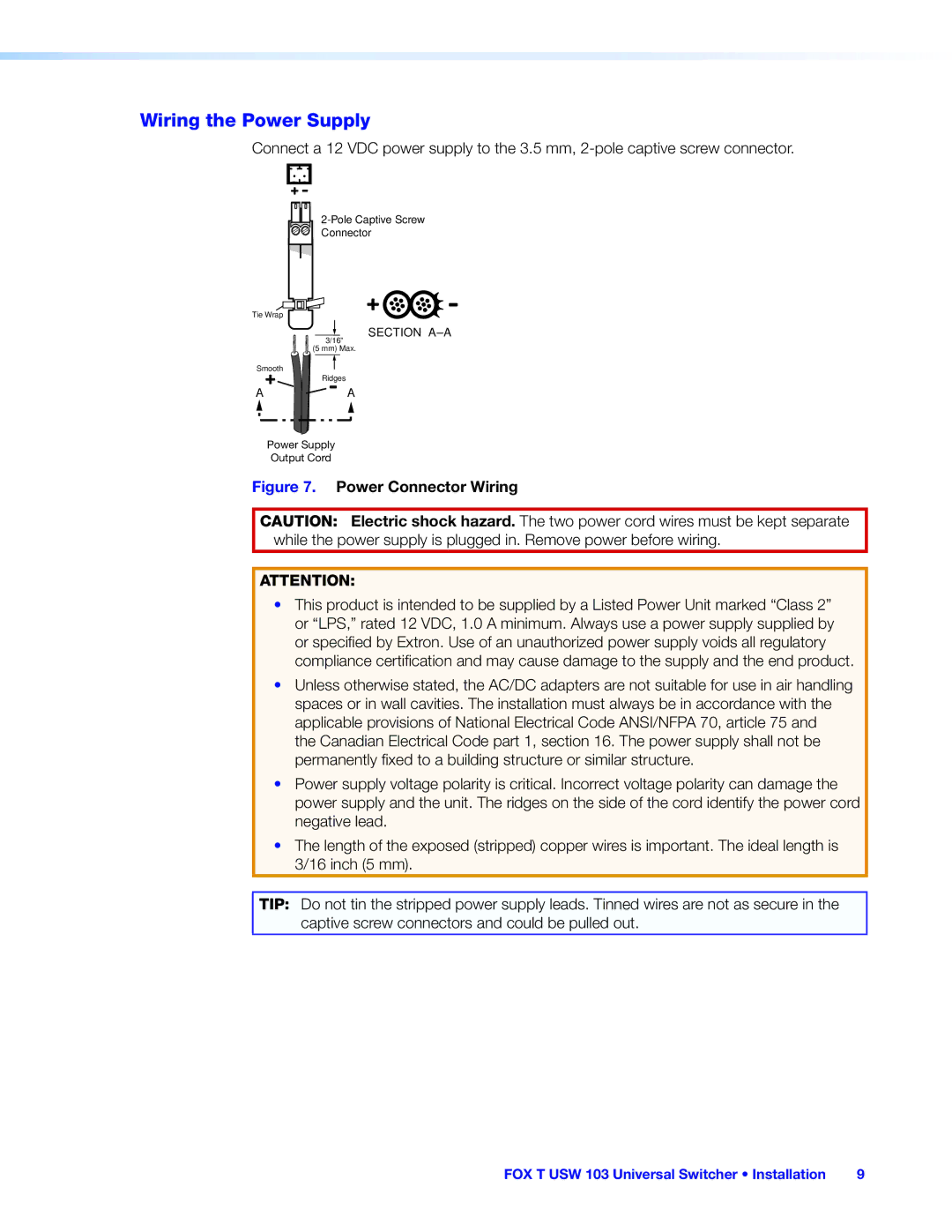
Connect a 12 VDC power supply to the 3.5 mm,
Connector
Tie Wrap
| SECTION |
| 3/16” |
| (5 mm) Max. |
Smooth |
|
| Ridges |
A | A |
Power Supply
Output Cord
Figure 7. Power Connector Wiring
CAUTION: Electric shock hazard. The two power cord wires must be kept separate while the power supply is plugged in. Remove power before wiring.
ATTENTION:
•This product is intended to be supplied by a Listed Power Unit marked “Class 2” or “LPS,” rated 12 VDC, 1.0 A minimum. Always use a power supply supplied by or specified by Extron. Use of an unauthorized power supply voids all regulatory
compliance certification and may cause damage to the supply and the end product.
•Unless otherwise stated, the AC/DC adapters are not suitable for use in air handling spaces or in wall cavities. The installation must always be in accordance with the applicable provisions of National Electrical Code ANSI/NFPA 70, article 75 and the Canadian Electrical Code part 1, section 16. The power supply shall not be permanently fixed to a building structure or similar structure.
•Power supply voltage polarity is critical. Incorrect voltage polarity can damage the power supply and the unit. The ridges on the side of the cord identify the power cord negative lead.
•The length of the exposed (stripped) copper wires is important. The ideal length is 3/16 inch (5 mm).
TIP: Do not tin the stripped power supply leads. Tinned wires are not as secure in the captive screw connectors and could be pulled out.
FOX T USW 103 Universal Switcher • Installation | 9 |