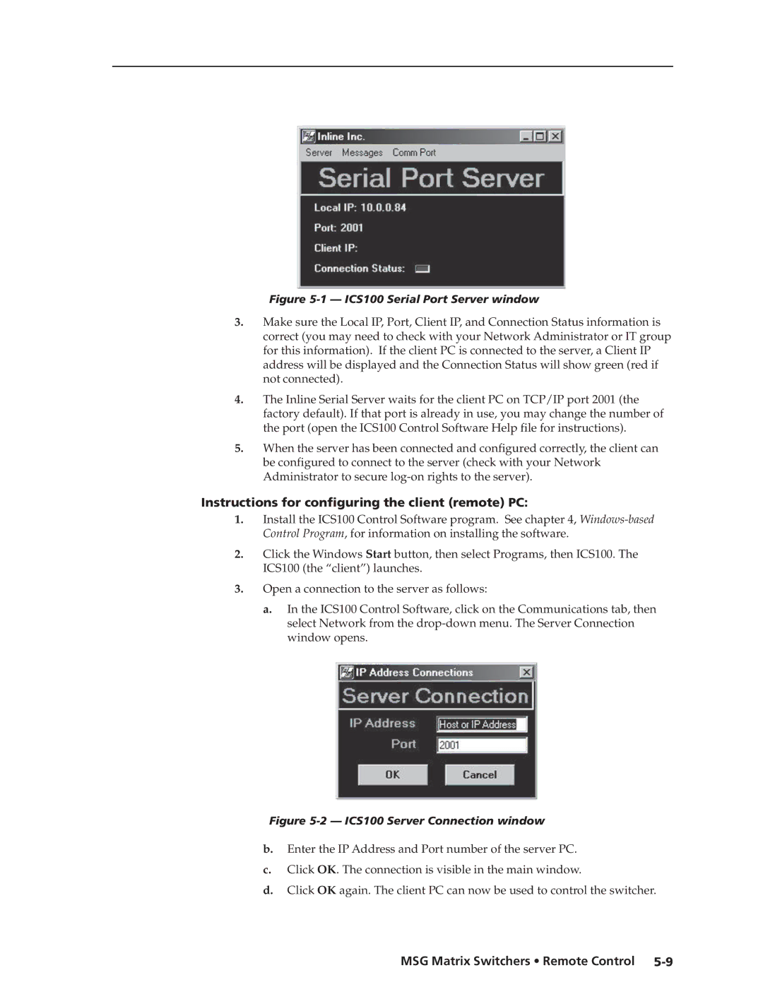
Figure 5-1 — ICS100 Serial Port Server window
3.Make sure the Local IP, Port, Client IP, and Connection Status information is correct (you may need to check with your Network Administrator or IT group for this information). If the client PC is connected to the server, a Client IP address will be displayed and the Connection Status will show green (red if not connected).
4.The Inline Serial Server waits for the client PC on TCP/IP port 2001 (the factory default). If that port is already in use, you may change the number of the port (open the ICS100 Control Software Help file for instructions).
5.When the server has been connected and configured correctly, the client can be configured to connect to the server (check with your Network Administrator to secure
Instructions for configuring the client (remote) PC:
1.Install the ICS100 Control Software program. See chapter 4,
2.Click the Windows Start button, then select Programs, then ICS100. The ICS100 (the “client”) launches.
3.Open a connection to the server as follows:
a.In the ICS100 Control Software, click on the Communications tab, then select Network from the
Figure 5-2 — ICS100 Server Connection window
b.Enter the IP Address and Port number of the server PC.
c.Click OK. The connection is visible in the main window.
d.Click OK again. The client PC can now be used to control the switcher.
