Matrix Switchers
MSG0804 and MSG0808
Precautions
Safety Instructions English
Consignes de Sécurité Français
Sicherheitsanleitungen Deutsch
Rack mounting the MSG0808
Connecting the MSG0808
Quick Start MSG0804 and MSG0808
Quick Start MSG0804 and MSG0808, cont’d
Operation
Table of Contents
Table of Contents, cont’d
One
Introduction
About the MSG Matrix Switchers
MSG Matrix Switcher Features
MSG Matrix Switchers Introduction
Introduction
Flexible Control Options
This page intentionally left blank
Installation
Two
Installation
Mounting the Switcher
MSG Matrix Switchers Installation
Tabletop use
Rear Panel Connectors
Video Inputs Video Outputs
Installation, cont’d
RS-485 Half Duplex Connection
Connecting the MSG0804 and MSG0808
MSG0808 installation example
Installation, cont’d
Audio input and output
Unbalanced audio
Balanced audio
Vertical Interval Switching
Connecting the external sync signal
This page intentionally left blank
Three
Operation
Operation
Front Panel Features
MSG Matrix Switchers Operation
Connecting inputs with outputs
Preset configurations
Front Panel Operation
Miscellaneous front panel functions
Operation, cont’d
Selecting the switching level audio versions only
Reset to factory default
Four
Windows-based Control Program
Windows-based Control Program, Cont’d
Installing the Windows-based ICS100 Control Software
Using the Software
Using the control panel
ICS100 Interface screen MSG switcher controls options
Setting volume levels
Adjusting output volume levels
Defining input icons and labels
Creating a new patch
Adjusting input volume levels
ICS100 Set Output Volume window
Setting and using presets
Opening the Options menu
VIS Enable
Enable Response
Using Terminal Comm
Resetting the unit
This page intentionally left blank
Remote Control
Five
MSG Matrix Switchers Remote Control
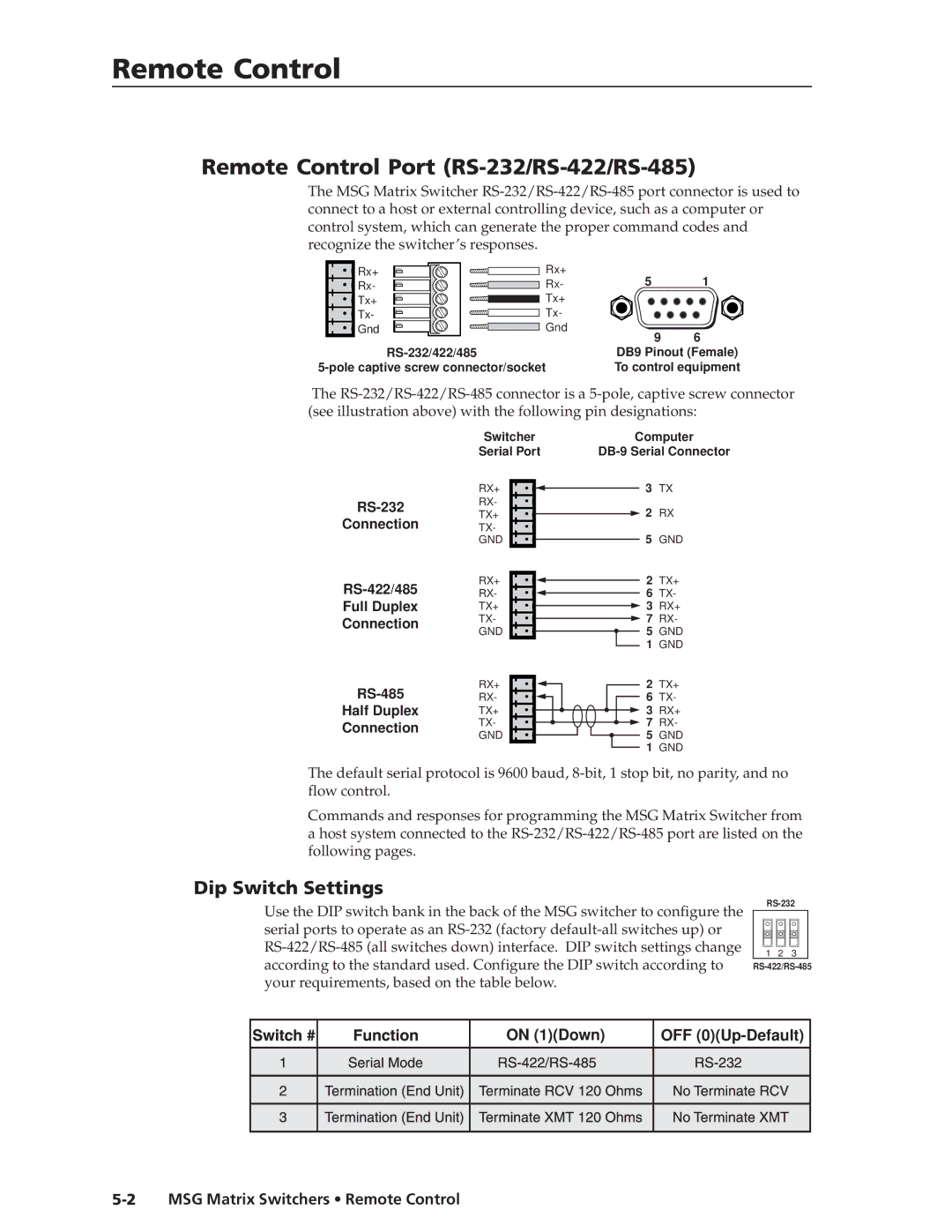
Remote Control
Dip Switch Settings
Using the command table
Host-to-MSG Matrix Switcher Communications
Addressing commands
Remote Control, cont’d
Command Table
Set-up commands
Command Description
Switching commands
Volume commands
Switching levels audio models only
Blank output
Mute all outputs
Stop volume ramp
Remote Control from a Network
Preset commands
Enabling remote control of the switcher over a network
Change input volume level global
Instructions for configuring the client remote PC
ICS100 Serial Port Server window
Adjusting response time
Adjusting the response time
Stopping communication
Stopping communications from the server PC
CTL120-2 IR Remote Control
Press this button first
Remote Control, cont’d
Specifications
AAppendix
Specifications
Video
Video input
Video output
MSG Matrix Switchers Specifications A-3
Sync
Audio audio models only
Audio input
Specifications MSG0804 and MSG0808
Control/remote switcher
MSG Matrix Switchers Specifications
General
BAppendix
Reference Information
Updating the Firmware
To update the firmware
Reference Information
MSG Matrix Switchers Reference Information
Installing Custom Engraved Nameplates
Installing the custom nameplates
MSG Matrix Switcher part numbers
Optional accessories
Reference Information, cont’d
Part Numbers
Plenum Seventeen Conductor Installation Cable
Assorted connectors BNC connectors
Pre-cut cables
Extron Part BNC-4 Mini HR Cable
This page intentionally left blank
FCC Class a Notice Extron’s Warranty
Extron Electronics, USA