MTP U R RSA SEQ, MTP U R RS SEQ, MTP U R RS, and MTP U R A
User’s Guide
Rev. B
Safety Instructions English
Precautions
Consignes de Sécurité Français
Sicherheitsanleitungen Deutsch
安全须知 中文
Precautions
FCC Class A Notice
Page
Front Panel Controls and Indicators
Table of Contents
MTPT U R Series Table of Contents
About the MTP Universal Receivers
About this Manual
Introduction
About the MTP Universal Receivers
Figure 1 - MTP U R series features
MTP U R Series Introduction
TP cable advantages
Introduction, cont’d
Transmission distance
4 MTP U R Series Introduction
Setting JMP1 for RS-232 communication
Receiver Jumpers
Figure 3 - Setting jumper 1 to uni-directional
MTP U R Series Introduction
Introduction, cont’d
Transmitter Jumper
6 MTP U R Series Introduction
Figure 4 - Inverting sync with jumpers 2 and
Figure 5 - MTP U R and MTPX switcher
Application Diagrams
Figure 6 - MTP U R and SW4 MTP T 15HD A switcher
Figure 7 - MTP U R and Xpoint 450 switcher
Installation
Installation
8 MTP U R Series Installation
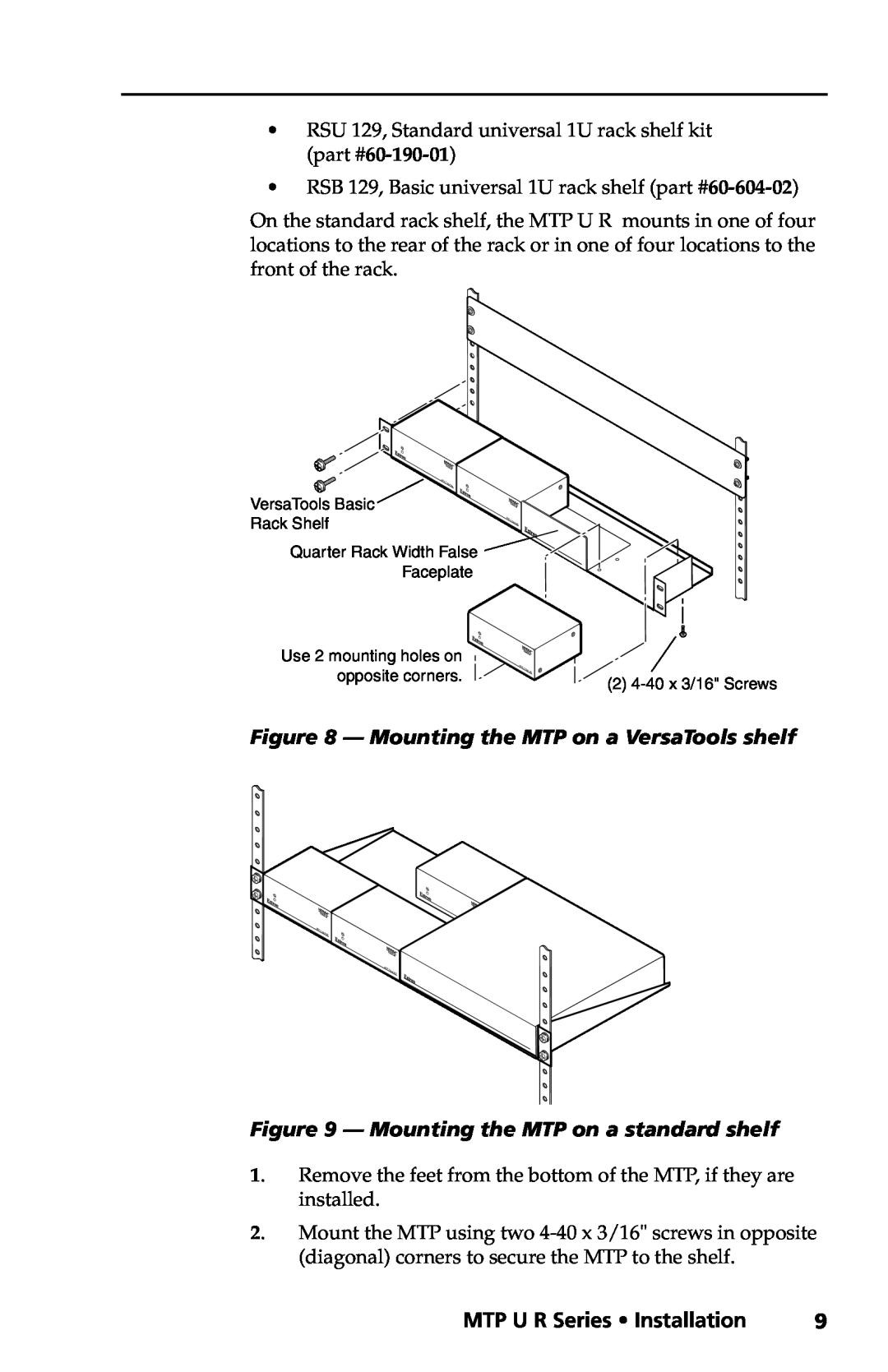
Figure 8 - Mounting the MTP on a VersaTools shelf
MTP U R Series Installation
Figure 9 - Mounting the MTP on a standard shelf
10 MTP U R Series Installation
Installation, cont’d
Back of the rack mounting
Figure 10 - Attaching the back of the rack kit
Figure 11 - Typical back of the rack installations
MTP U R Series Installation
ENTER PRESET
Use the optional mounting kit MBU 123, furniture
12 MTP U R Series Installation
Installation, cont’d
holes, 1/4 6.3 mm deep in the mounting surface at the
until just less than 1/4 6 mm of the screw head protrudes
MTP U R Series Installation
Connections and Settings
Rear panel connectors and features for the MTP U R series of
Figure 13 - Receivers’ rear panel features
14 MTP U R Series Installation
Installation, cont’d
See “TP cable termination” to wire the RJ-45 connectors
BNC connectors for component Y, R-Y, and B-Y video output
RS-232 communication. Wire the connector as shown below
MTP U R Series Installation
Figure 14 - Pin assignments for RS-232 wiring
Figure 15 - Audio connector wiring
Power supply wiring
Installation, cont’d
16 MTP U R Series Installation
Figure 16 - Power connector wiring
TP cable termination
MTP U R Series Installation
Figure 17 - TP cable termination
Figure 18 - MTP pin assignments
18 MTP U R Series Installation
Installation, cont’d Front Panel Controls and Indicators
Front panel features on the MTP U R receivers are shown below
SIGNAL
Green, and Blue LEDS D all turn off. Release the button
MTP U R Series Installation
Peaking and Level Adjustment
Installation, cont’d
20 MTP U R Series Installation
MTP U R Series Installation
Skew Delay Compensation
SEQ receiver skew compensation
22 MTP U R Series Installation
Installation, cont’d
Non-SEQ receivers skew compensation
Specifications
Specifications
MTP U R Series Specifications
Specifications, cont’d
MTP U R Series Specifications
N Specifications are subject to change without notice
General
N Protocol is mirrored between the transmitter and the receiver
Accessories
Specifications, cont’d Part Numbers
RJ-45 connector
26 MTP U R Series Specifications
USA, Canada, South America
Extron’s Warranty
and Central America
Asia
Extron USA - West
2008 Extron Electronics. All rights reserved
Extron USA - East
Extron EMEA