NOTE: If needed, Extron recommends using a
The kit provides a convenient means to replace the XPA’s IEC power cord with conduit, where required by local codes.
WARNING: Failure to follow these instructions may result in serious injury. Make sure that the source device and the XPA are turned off and disconnected from the power source before you begin.
UL Requirements
The Underwriters Laboratories (UL) requirements listed below pertain to the installation of
the flexible conduit onto a XPA 1002 or XPA 2001.
•This unit is not to be used beyond its rated voltage range.
•This unit must be wired to a UL listed distribution box.
NOTE: The UL approved electrical distribution box is not included with either the XPA or the Flexible Conduit Adapter Kit; the installer is responsible for obtaining and installing the box.
Installing the Flexible Conduit Kit
Install flexible conduit to the XPA by following the steps below.
1.Unplug the IEC power cord from the power amplifier.
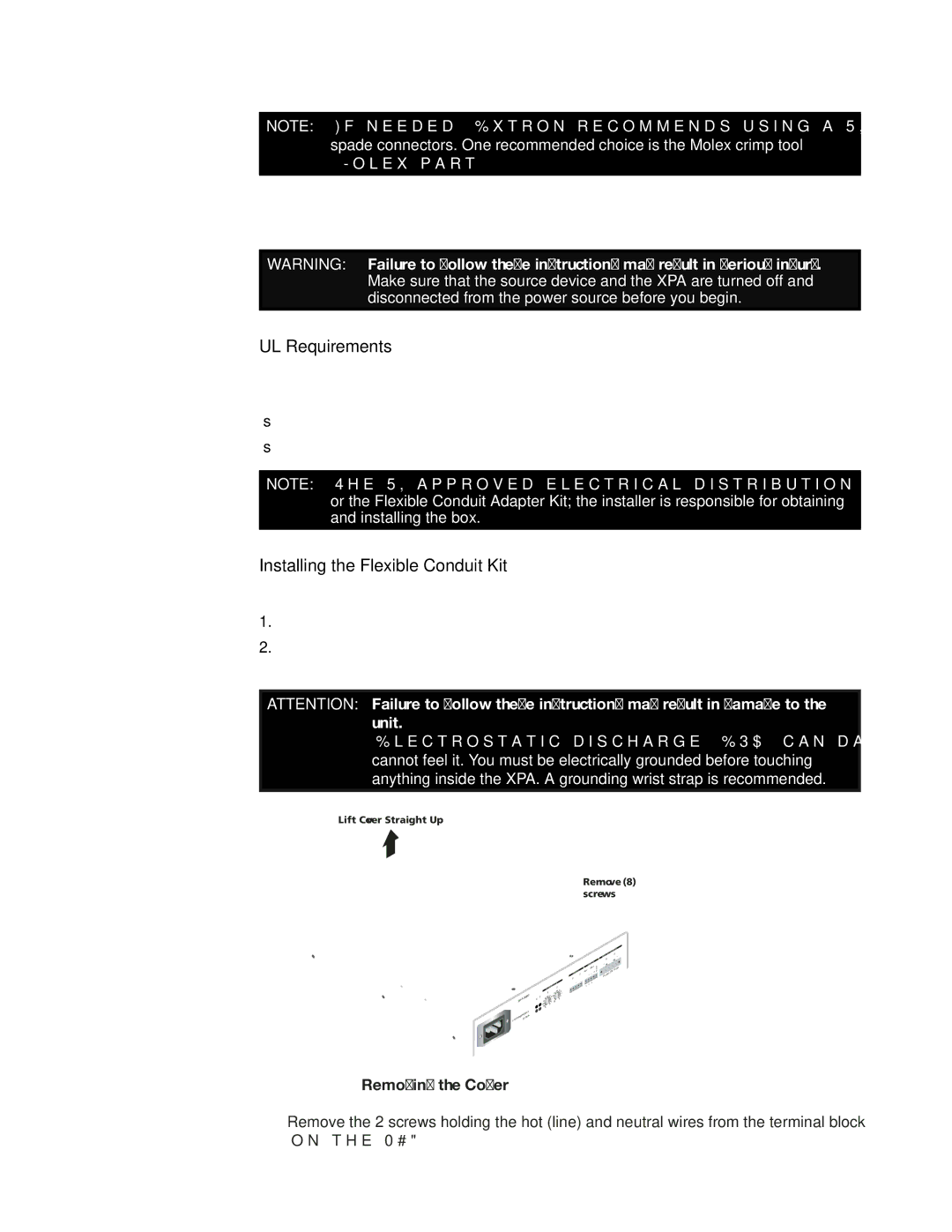
2.Remove the 8 screws from the top and sides of the XPA and lift off the cover. See the following illustration.
ATTENTION: Failure to follow these instructions may result in damage to the unit.
Electrostatic discharge (ESD) can damage IC chips even though you cannot feel it. You must be electrically grounded before touching anything inside the XPA. A grounding wrist strap is recommended.
Lift Cover Straight Up
Remove (8) screws
0.5A,
z
A 1002
XP
T OTEC ![]() LIMITER/PRSIGNAL
LIMITER/PRSIGNAL
2 1
ATTENU | ATION | |
2 | ||
1 |
| 10 8 |
| 12 | |
10 8 | 6 14 | |
12 | 4 | 0 |
14 | 2 | ∞ |
180
26∞
6 4
2
INPUTS2 1
|
| REMOTE | |
|
|
| 50mA |
10 | V |
| G |
V | C | G | |
STANDBY
|
|
| S |
| / 4Ω | OUTPUT | |
8Ω |
| 2 | |
| 1 |
|
|
|
| 2 WI | RING |
|
|
| |
CLASS |
|
| |
Figure 5. Removing the Cover
3.Remove the 2 screws holding the hot (line) and neutral wires from the terminal block on the PCB.
XTRA Series • Installation | 7 |
