Rear Panel Features and Operation
1
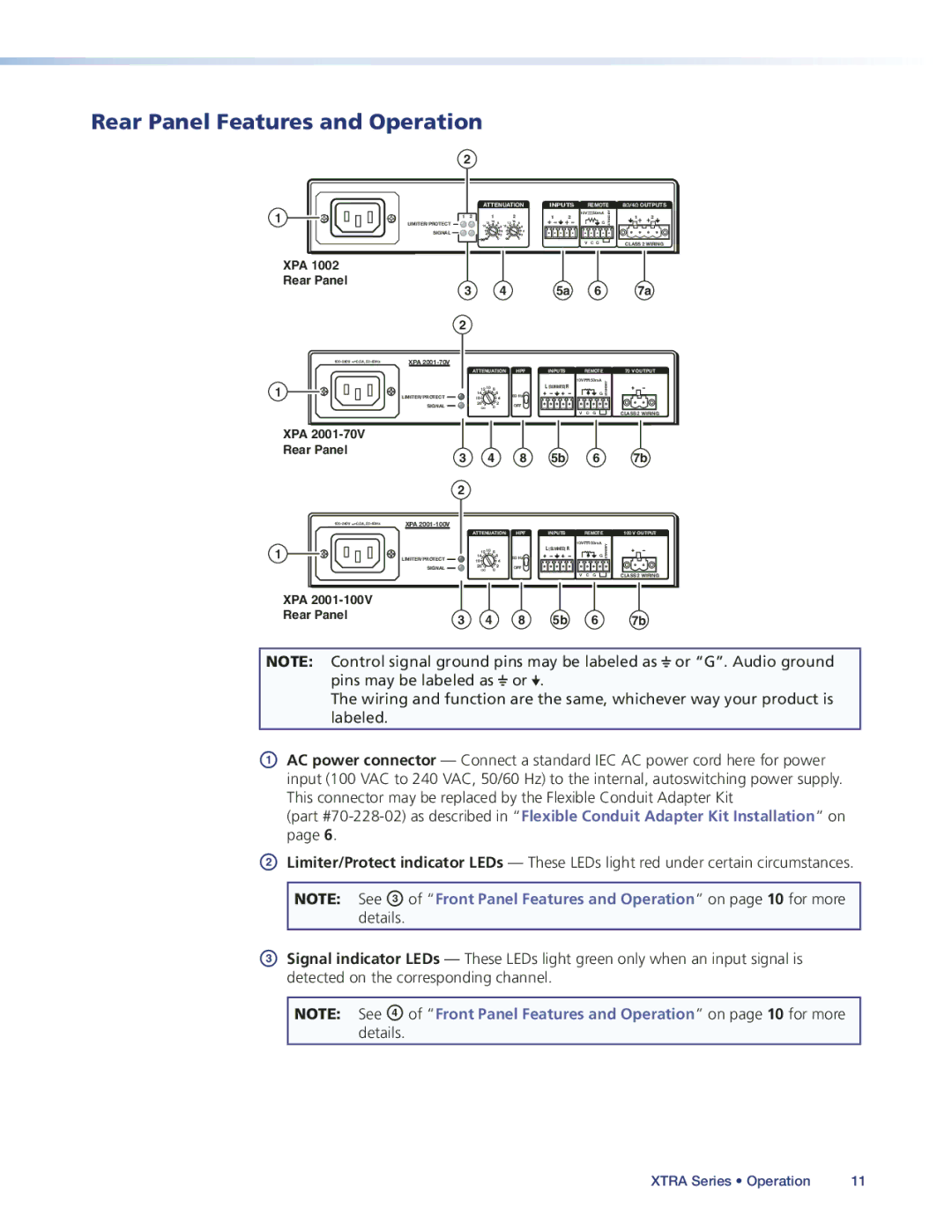
XPA 1002
Rear Panel
![]() 0.5A,
0.5A,
1
XPA
Rear Panel
![]() 0.5A,
0.5A,
1
XPA
Rear Panel
2 |
|
|
|
|
|
|
|
|
|
|
|
|
|
| |
LIMITER/PROTECT | ATTENUATION | INPUTS |
| REMOTE | 8Ω/4Ω OUTPUTS | ||||||||||
| 12 10 | 8 | 12 | 10 | 8 |
|
|
|
| G | STANDBY |
|
| ||
1 | 2 | 1 |
|
| 2 |
| 1 | 2 | 10V | 50mA |
|
| 1 | 2 | |
|
|
|
|
|
|
|
| ||||||||
| 14 |
| 6 14 |
|
| 6 |
|
|
|
|
|
|
|
|
|
SIGNAL |
|
| 4 |
|
| 4 |
|
|
|
|
|
|
|
|
|
|
| 2 |
|
| 2 |
|
|
|
|
|
|
|
|
| |
|
|
| 0 |
|
| 0 |
|
|
| V C G |
|
|
|
| |
|
|
|
|
|
|
|
|
|
|
|
| CLASS 2 WIRING | |||
3 |
| 4 |
|
|
|
| 5a |
|
| 6 |
|
|
| 7a | |
2 |
|
|
|
|
|
|
|
|
|
|
|
|
|
|
|
XPA |
|
|
|
|
|
|
|
|
|
|
|
|
|
|
|
| ATTENUATION |
|
| HPF | INPUTS |
| REMOTE |
|
| 70 V OUTPUT | |||||
| 14 |
| 6 |
|
|
|
|
| 10V |
| 50mA | STANDBY |
|
|
|
|
|
|
|
| L (SUMMED) R |
|
| G |
|
|
| ||||
| 12 10 8 |
|
|
|
|
|
|
|
|
|
|
|
|
| |
LIMITER/PROTECT | 18 |
| 4 |
| 80 Hz |
|
|
|
|
|
|
|
|
| |
|
|
|
|
|
|
|
|
|
|
|
|
| |||
SIGNAL | 26∞ | 0 2 |
| OFF |
|
| V | C | G |
|
| CLASS 2 WIRING | |||
3 | 4 | 8 | 5b | 6 | 7b |
2
XPA |
|
|
|
|
|
|
|
| ATTENUATION | HPF | INPUTS | REMOTE | 100 V OUTPUT | ||
| 14 | 6 |
| 10V |
| 50mA | STANDBY |
|
| L (SUMMED) R |
| G | |||
| 12 10 | 8 |
|
|
|
|
|
LIMITER/PROTECT | 18 | 4 | 80 Hz |
|
|
|
|
|
|
|
|
| |||
SIGNAL | 26∞ | 0 2 | OFF | V | C | G | CLASS 2 WIRING |
3 | 4 | 8 | 5b | 6 | 7b |
NOTE: Control signal ground pins may be labeled as ![]() or “G”. Audio ground pins may be labeled as
or “G”. Audio ground pins may be labeled as ![]() or
or ![]() .
.
The wiring and function are the same, whichever way your product is labeled.
AAC power connector — Connect a standard IEC AC power cord here for power input (100 VAC to 240 VAC, 50/60 Hz) to the internal, autoswitching power supply.
This connector may be replaced by the Flexible Conduit Adapter Kit
(part
BLimiter/Protect indicator LEDs — These LEDs light red under certain circumstances.
NOTE: See C of “Front Panel Features and Operation” on page 10 for more
details.
CSignal indicator LEDs — These LEDs light green only when an input signal is detected on the corresponding channel.
NOTE: See D of “Front Panel Features and Operation” on page 10 for more
details.
XTRA Series • Operation | 11 |