|
|
|
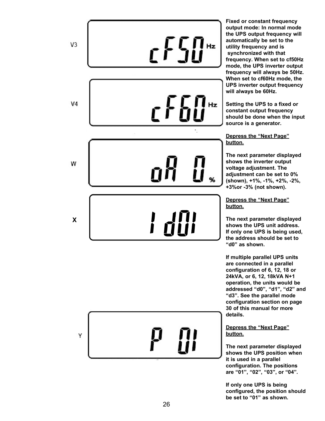
| Fixed or constant frequency |
|
|
|
| output mode: In normal mode |
|
|
|
| the UPS output frequency will |
|
|
|
| automatically be set to the |
|
|
|
| utility frequency and is |
|
|
|
| synchronized with that |
|
|
|
| frequency. When set to cf50Hz |
|
|
|
| mode, the UPS inverter output |
|
|
|
| frequency will always be 50Hz. |
|
|
|
| When set to cf60Hz mode, the |
|
|
|
| UPS inverter output frequency |
|
|
|
| will always be 60Hz. |
|
|
|
| Setting the UPS to a fixed or |
|
|
|
| constant output frequency |
|
|
|
| should be done when the input |
|
|
|
| source is a generator. |
|
|
|
| Depress the “Next Page” |
|
|
|
| |
|
|
|
| |
|
|
|
| button. |
|
|
|
| The next parameter displayed |
|
|
|
| shows the inverter output |
|
|
|
| voltage adjustment. The |
|
|
|
| adjustment can be set to 0% |
|
|
|
| (shown), +1%, |
|
|
|
| +3%or |
|
|
|
| Depress the “Next Page” |
|
|
|
| button. |
X |
|
| The next parameter displayed | |
shows the UPS unit address. If only one UPS is being used, the address should be set to “d0” as shown.
If multiple parallel UPS units are connected in a parallel configuration of 6, 12, 18 or 24kVA, or 6, 12, 18kVA N+1 operation, the units would be addressed “d0”, “d1”, “d2” and “d3”. See the parallel mode configuration section on page 30 of this manual for more details.
Depress the “Next Page” button.
The next parameter displayed shows the UPS position when it is used in a parallel configuration. The positions are “01”, “02”, “03”, or “04”.
If only one UPS is being configured, the position should be set to “01” as shown.
26
