|
|
|
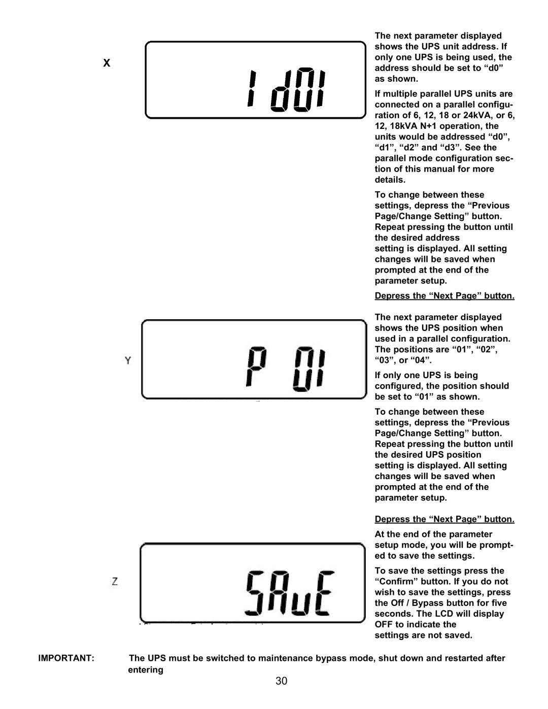
| The next parameter displayed |
|
|
|
| shows the UPS unit address. If |
| X |
|
| only one UPS is being used, the |
|
|
| address should be set to “d0” | |
|
|
|
| |
|
|
|
| as shown. |
|
|
|
| If multiple parallel UPS units are |
|
|
|
| connected on a parallel configu- |
|
|
|
| ration of 6, 12, 18 or 24kVA, or 6, |
|
|
|
| 12, 18kVA N+1 operation, the |
|
|
|
| units would be addressed “d0”, |
|
|
|
| “d1”, “d2” and “d3”. See the |
|
|
|
| parallel mode configuration sec- |
|
|
|
| tion of this manual for more |
|
|
|
| details. |
|
|
|
| To change between these |
|
|
|
| settings, depress the “Previous |
|
|
|
| Page/Change Setting” button. |
|
|
|
| Repeat pressing the button until |
|
|
|
| the desired address |
|
|
|
| setting is displayed. All setting |
|
|
|
| changes will be saved when |
|
|
|
| prompted at the end of the |
|
|
|
| parameter setup. |
|
|
|
| Depress the “Next Page” button. |
|
|
|
| The next parameter displayed |
|
|
|
| shows the UPS position when |
|
|
|
| used in a parallel configuration. |
|
|
|
| The positions are “01”, “02”, |
|
|
|
| “03”, or “04”. |
|
|
|
| If only one UPS is being |
|
|
|
| configured, the position should |
|
|
|
| be set to “01” as shown. |
|
|
|
| To change between these |
|
|
|
| settings, depress the “Previous |
|
|
|
| Page/Change Setting” button. |
|
|
|
| Repeat pressing the button until |
|
|
|
| the desired UPS position |
|
|
|
| setting is displayed. All setting |
|
|
|
| changes will be saved when |
|
|
|
| prompted at the end of the |
|
|
|
| parameter setup. |
|
|
|
| Depress the “Next Page” button. |
|
|
|
| At the end of the parameter |
|
|
|
| setup mode, you will be prompt- |
|
|
|
| ed to save the settings. |
|
|
|
| To save the settings press the |
|
|
|
| “Confirm” button. If you do not |
|
|
|
| wish to save the settings, press |
|
|
|
| the Off / Bypass button for five |
|
|
|
| seconds. The LCD will display |
|
|
|
| OFF to indicate the |
|
|
|
| settings are not saved. |
IMPORTANT: |
| The UPS must be switched to maintenance bypass mode, shut down and restarted after | ||
|
| entering | ||
30