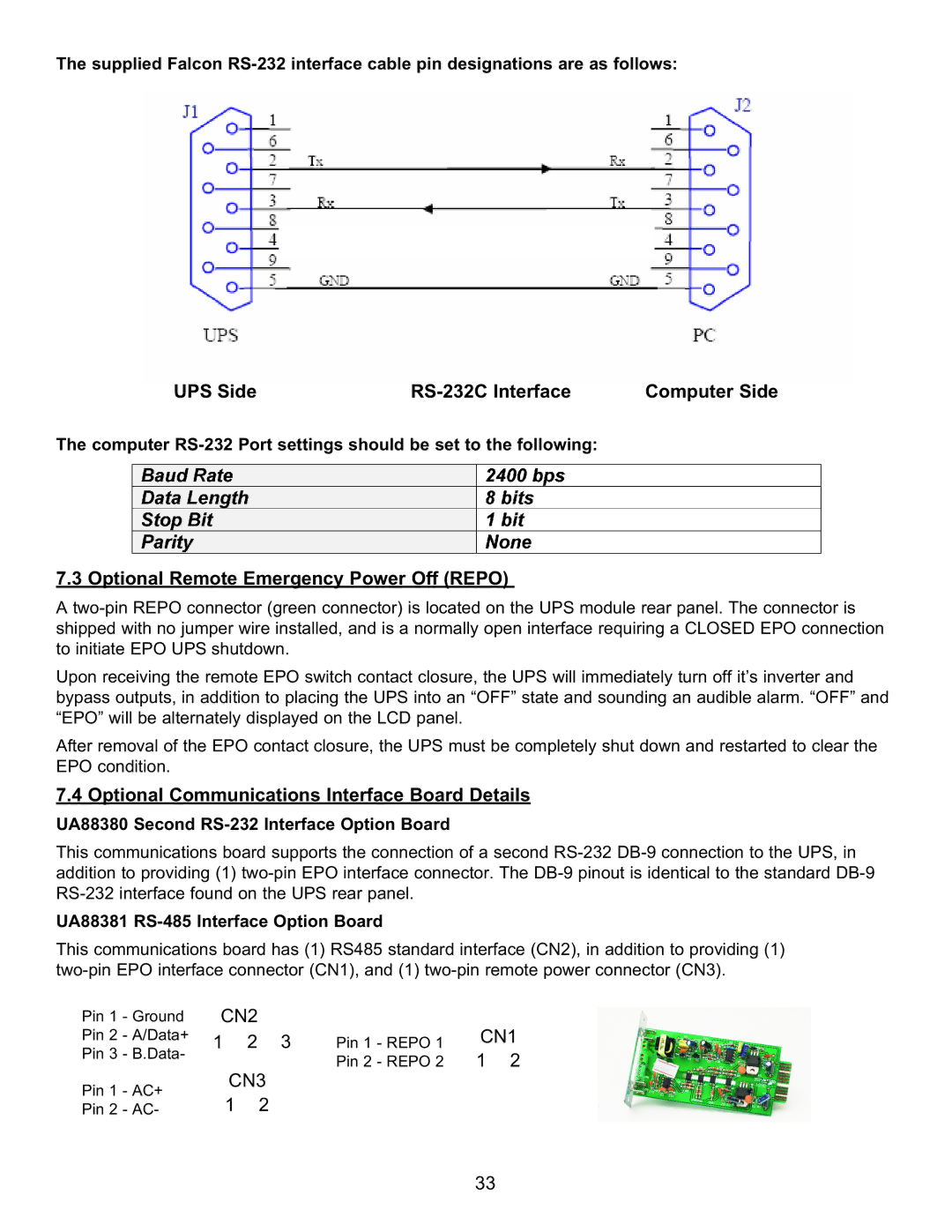
The supplied Falcon
UPS Side |
| Computer Side |
|
|
|
The computer
7.3 Optional Remote Emergency Power Off (REPO)
A
Upon receiving the remote EPO switch contact closure, the UPS will immediately turn off it’s inverter and bypass outputs, in addition to placing the UPS into an “OFF” state and sounding an audible alarm. “OFF” and “EPO” will be alternately displayed on the LCD panel.
After removal of the EPO contact closure, the UPS must be completely shut down and restarted to clear the EPO condition.
7.4 Optional Communications Interface Board Details
UA88380 Second RS-232 Interface Option Board
This communications board supports the connection of a second
UA88381 RS-485 Interface Option Board
This communications board has (1) RS485 standard interface (CN2), in addition to providing (1)
Pin 1 - Ground | CN2 |
| |||
Pin 2 | - A/Data+ | 1 | 2 | 3 | |
Pin 3 | - B.Data- | ||||
|
|
| |||
Pin 1 | - AC+ |
| CN3 | ||
| 1 | 2 | |||
Pin 2 | - AC- |
| |||
Pin 1 - REPO 1 | CN1 |
| |
Pin 2 - REPO 2 | 1 2 |
33