2.1 Output Power Distribution Center
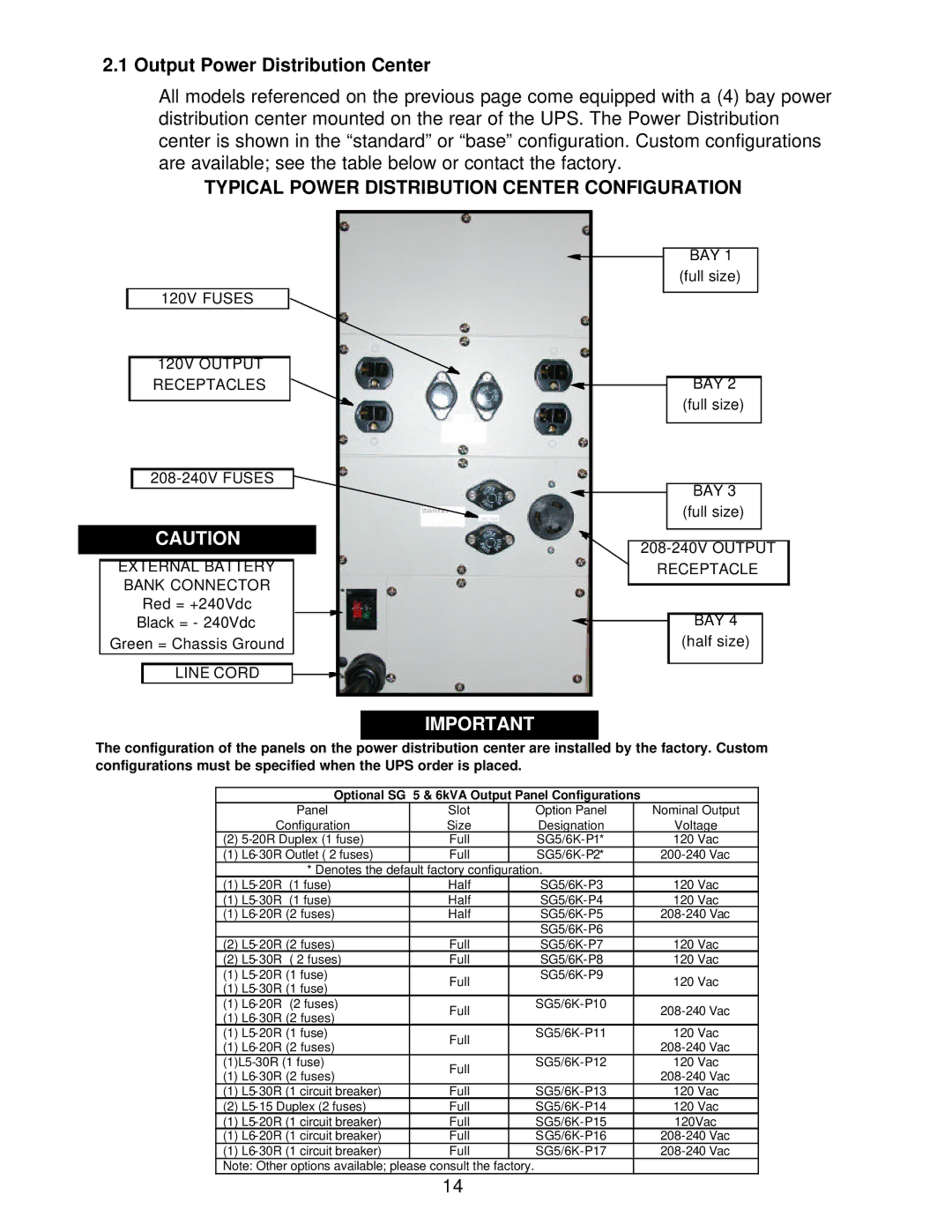
All models referenced on the previous page come equipped with a (4) bay power distribution center mounted on the rear of the UPS. The Power Distribution center is shown in the “standard” or “base” configuration. Custom configurations are available; see the table below or contact the factory.
TYPICAL POWER DISTRIBUTION CENTER CONFIGURATION
|
|
|
|
|
|
|
|
|
|
|
|
|
|
|
|
|
|
|
|
|
|
|
|
| BAY 1 |
|
|
|
|
|
|
|
|
|
|
|
|
|
|
| |
|
|
|
|
|
|
|
|
|
|
| (full size) |
|
|
|
|
|
|
|
|
|
|
|
| ||||
|
|
| 120V FUSES |
|
|
|
|
|
|
| |||
|
|
|
|
|
|
|
|
|
|
| |||
|
|
| 120V OUTPUT |
|
|
|
|
|
|
|
|
|
|
|
|
| RECEPTACLES |
|
|
|
| BAY 2 |
|
| |||
|
|
|
|
|
| ||||||||
|
|
|
|
|
|
|
|
|
|
| (full size) |
|
|
|
|
|
|
|
|
|
|
|
|
|
|
| |
|
|
|
|
|
|
|
|
|
|
|
|
|
|
|
|
|
|
|
|
|
|
|
| ||||
|
|
|
|
|
|
|
|
|
| ||||
|
|
|
|
|
|
|
|
|
|
| BAY 3 |
| |
|
|
|
|
|
|
|
|
|
|
|
|
| |
|
|
|
|
|
|
|
|
|
|
|
|
| |
|
|
|
|
|
|
|
|
|
|
| (full size) |
|
|
|
|
|
|
|
|
|
|
|
|
|
|
|
|
|
|
| CAUTION |
|
|
|
|
|
|
|
| ||
|
|
|
|
|
|
| |||||||
|
|
|
|
|
|
|
|
|
| ||||
|
|
|
|
|
|
|
|
|
|
|
|
|
|
| EXTERNAL BATTERY |
|
| RECEPTACLE | |||||||||
| BANK CONNECTOR |
|
|
|
|
|
|
|
|
| |||
|
|
|
|
|
|
|
|
|
| ||||
|
|
| Red = +240Vdc |
|
|
|
|
|
|
|
|
| |
|
| Black = - 240Vdc |
|
|
|
|
|
| BAY 4 |
| |||
|
|
|
|
| |||||||||
| Green = Chassis Ground |
|
|
|
|
|
| (half size) |
| ||||
|
|
|
|
|
|
|
|
|
|
|
|
|
|
|
|
| LINE CORD |
|
|
|
|
|
|
|
|
|
|
|
|
|
|
|
|
|
|
|
|
|
|
|
|
|
|
|
|
|
|
|
|
|
|
|
|
|
|
IMPORTANT
The configuration of the panels on the power distribution center are installed by the factory. Custom configurations must be specified when the UPS order is placed.
Optional SG 5 & 6kVA Output Panel Configurations
| Panel | Slot |
| Option Panel | Nominal Output |
| Configuration | Size |
| Designation | Voltage |
(2) | Full |
| 120 Vac | ||
(1) | Full |
| |||
| * Denotes the default factory configuration. |
| |||
(1) | Half |
| 120 Vac | ||
(1) | Half |
| 120 Vac | ||
(1) | Half |
| |||
|
|
|
|
| |
(2) | Full |
| 120 Vac | ||
(2) | Full |
| 120 Vac | ||
(1) | Full |
| 120 Vac | ||
(1) |
|
| |||
|
|
|
| ||
(1) | Full |
| |||
(1) |
|
| |||
|
|
|
| ||
(1) | Full |
| 120 Vac | ||
(1) |
|
| |||
|
|
| |||
Full |
| 120 Vac | |||
(1) |
|
| |||
|
|
| |||
(1) | Full |
| 120 Vac | ||
(2) | Full |
| 120 Vac | ||
(1) | Full |
| 120Vac | ||
(1) | Full |
| |||
(1) | Full |
| |||
Note: Other options available; please consult the factory. |
|
| |||
14