INSTALLATION AND ADJUSTMENT

PLEASE READ COMPLETELY BEFORE BEGINNING INSTALLATION!

CAUTION: The TM-2000 is not to be used on electric furnaces, heat pumps, or in locations where the air temperature could drop below 40°F. The mounting position of the mounting position of the TM-2000 is very important. Read all installation instructions prior to installing your TM-2000 humidifier. Save these instructions for future reference of replacement parts and optional components.

1.Locate the SUPPLY PLENUM of your warm air furnace. The supply plenum is the main duct of the furnace that directs heated air to the home. (See Figures 1-3) A minimum of 120°F is required in the furnace supply plenum to allow for proper humidifier operation. Most oil and gas fired furnaces are capable of providing air flow of this temperature. If this condition cannot be met, a different type of humidification system must be considered.

2.Determine the optimal location for the Housing Assembly (See Figures 1-3, 5 & 8 for typical installations) by locating the warmest part of the plenum (close to the outlet of the furnace) that will satisfy these minimum requirements: (a) 120°F minimum air flow temperature in the supply plenum,

(b) 1 cubic foot minimum volume surrounding nozzle tip to prevent spray impingement on duct walls, or other obstacles. (See Figure 6) In certain installations, it may be necessary to further extend the nozzle using an optional Field Controls EK-1 Extender Kit. (See Figure 7) A 45o elbow fitting can also be installed to redirect the spray without extending the nozzle. If an air conditioning “A-COIL” with open sides exists at the furnace outlet, the Housing Assembly should be located in the area between the A-COIL and the furnace outlet. (See Figures 4, 5 & 8)

CAUTION: Use extreme caution when drilling or cutting any holes in the furnace plenum in order to avoid damaging the A-coil.

3.Following the instructions printed on the Housing Mounting Template, attach it to the plenum at the location determined in Step 2. MOUNT THE TEMPLATE RIGHT SIDE UP ON A VERTICAL SURFACE ONLY, ON THE SIDE OF THE PLENUM.

Figure 1

Figure 2

4.Cut and drill or punch holes in the plenum as indicated on the template, and completely remove the template when finished.

5.Carefully mount the TM-2000 Housing Assembly to the plenum using the four #8-15 x 3/4” long hex head sheet metal screws. Take care to avoid damage to the thermal sensing element.

6.Determine an appropriate location for the Remote Nozzle Bracket Assembly, being careful to maintain the minimum distances from the Housing Assembly and adjacent plenum walls and other structures, as shown in Figures 1-3. BE SURE THAT THE NOZZLE IS LOCATED DOWNSTREAM OF THE HOUSING ASSEMBLY, IN SUCH A WAY THAT THE MIST WILL NOT BE DIRECTED TOWARDS THE HOUSING ASSEMBLY. THE NOZZLE ASSEMBLY SHOULD BE MOUNTED RIGHT SIDE UP ON A VERTICAL SURFACE, ON THE SIDE OF THE PLENUM, WITH THE NOZZLE DIRECTLY ABOVE THE DRIP GUARD.

7.Following the instructions printed on the Remote Bracket Mounting Template, attach it to the plenum at the location determined in Step 6.

8.Cut and drill or punch holes in the plenum as indicated on the template, and completely remove the template when finished.

Page 2

Page 2
Image 2
Field Controls TM-2000 instruction manual

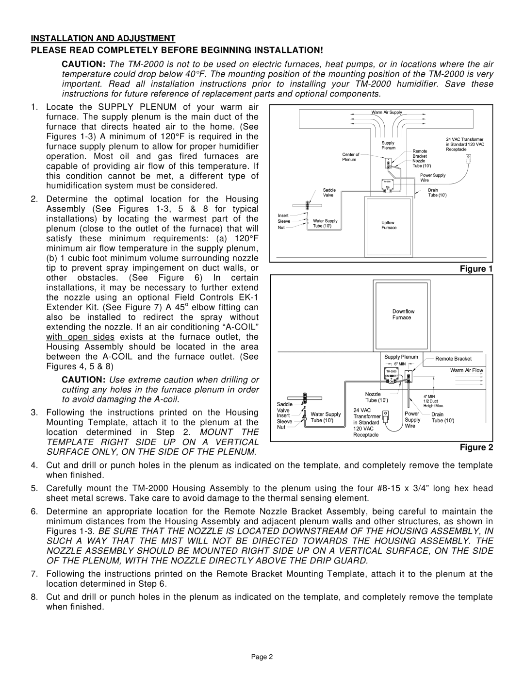
TM-2000 specifications

The Field Controls TM-2000 is a sophisticated air management system designed to enhance indoor air quality and energy efficiency in residential and commercial buildings. This advanced system employs cutting-edge technologies to ensure optimal performance and user-friendly operations.

One of the main features of the TM-2000 is its ability to effectively reduce airborne contaminants, including dust, allergens, and volatile organic compounds (VOCs). By utilizing a combination of mechanical filtration and advanced air purifying technologies, the TM-2000 helps create a healthier indoor environment. The system is equipped with a high-efficiency filter that captures particulate matter as small as 0.3 microns, ensuring that even the smallest pollutants are removed from the air.

The TM-2000 is designed with smart technology that allows for seamless integration with existing HVAC systems. It features a user-friendly interface that provides real-time monitoring of air quality levels, filter status, and system performance. This allows homeowners and building managers to stay informed and make necessary adjustments to maintain optimal indoor air quality.

Another key characteristic of the TM-2000 is its energy-efficient operation. The unit is engineered to minimize energy consumption while delivering powerful air purification. It incorporates programmable settings, allowing users to tailor operation times and intensity based on their schedules and the specific air quality needs of their spaces. This not only conserves energy but also reduces utility costs, making it an economical option for users.

The TM-2000 also stands out in its versatility. It is suitable for a wide range of applications, from residential homes to office buildings and industrial facilities. Its compact design enables easy installation and maintenance, making it user-friendly for both professionals and end-users.

Safety features are also integrated into the TM-2000, including automatic shutoff capabilities and indicators for filter replacement. These safeguards ensure that the system operates efficiently and protects both the unit and its users.

In conclusion, the Field Controls TM-2000 is a state-of-the-art solution for anyone looking to improve indoor air quality. With its advanced filtration technology, user-friendly interface, energy-efficient operation, and robust safety features, it represents a smart investment for healthier living and working environments.