Page 13 of 37 |
4.1.6.Map Descriptor Example 3: Clock Read:
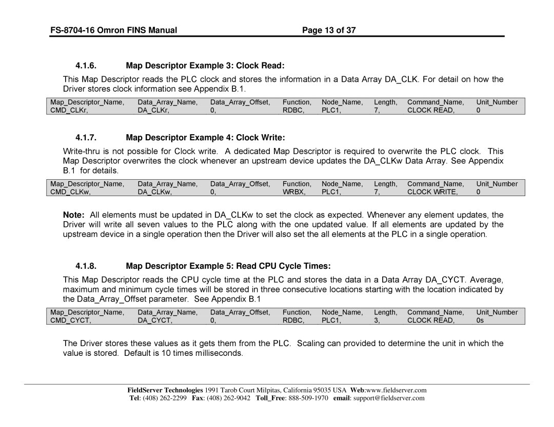
This Map Descriptor reads the PLC clock and stores the information in a Data Array DA_CLK. For detail on how the Driver stores clock information see Appendix B.1.
Map_Descriptor_Name, | Data_Array_Name, | Data_Array_Offset, | Function, | Node_Name, | Length, | Command_Name, | Unit_Number |
CMD_CLKr, | DA_CLKr, | 0, | RDBC, | PLC1, | 7, | CLOCK READ, | 0 |
4.1.7.Map Descriptor Example 4: Clock Write:
Map_Descriptor_Name, | Data_Array_Name, | Data_Array_Offset, | Function, | Node_Name, | Length, | Command_Name, | Unit_Number |
CMD_CLKw, | DA_CLKw, | 0, | WRBX, | PLC1, | 7, | CLOCK WRITE, | 0 |
Note: All elements must be updated in DA_CLKw to set the clock as expected. Whenever any element updates, the Driver will write all seven values to the PLC along with the one updated value. If all elements are updated by the upstream device in a single operation then the Driver will also set the all elements at the PLC in a single operation.
4.1.8.Map Descriptor Example 5: Read CPU Cycle Times:
This Map Descriptor reads the CPU cycle time at the PLC and stores the data in a Data Array DA_CYCT. Average, maximum and minimum cycle times will be stored in three consecutive locations starting with the location indicated by the Data_Array_Offset parameter. See Appendix B.1
Map_Descriptor_Name, | Data_Array_Name, | Data_Array_Offset, | Function, | Node_Name, | Length, | Command_Name, | Unit_Number |
CMD_CYCT, | DA_CYCT, | 0, | RDBC, | PLC1, | 3, | CLOCK READ, | 0s |
The Driver stores these values as it gets them from the PLC. Scaling can provided to determine the unit in which the value is stored. Default is 10 times milliseconds.
FieldServer Technologies 1991 Tarob Court Milpitas, California 95035 USA Web:www.fieldserver.com Tel: (408)
