Model VM08 Owner’s Manual ![]()
![]()
![]()
VM08 Initial State
The following explains what to do the first time you use the VM08 right out of the shipping carton. When the AC adaptor is plugged into the AC wall outlet and the power cord plugged into the DC IN connector, power will be applied and the VM08, and the display/operating panel lamps will light in the modes explained below. This is the same sa when the CPU is reset by pressing the RESET switch.
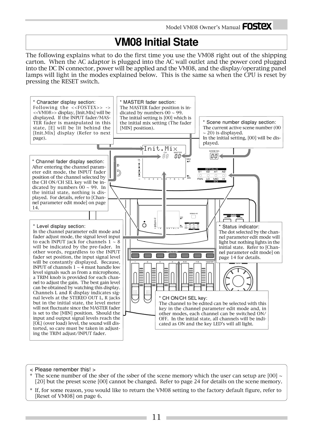
* Character display section: | * MASTER fader section: |
Following the <<FOSTEX>>
The MASTER fader position is in- dicated by numbers 00 ~ 99. The initial setting is [00] which is the initial mix setting (The fader [MIN] position).
*Scene number display section:
The current active scene number (00 ~ 20) is displayed.
In the initial setting, [00] will be dis- played.
*Channel fader display section:
After entering the channel param- eter edit mode, the INPUT fader position of the channel selected by the CH ON/CH SEL key will be in- dicated by numbers 00 ~ 99. In the initial state, nothing is dis- played. For details, refer to [Chan- nel parameter edit mode] on page 14.
* Level display section:
In the channel parameter edit mode and fader adjust mode, the signal level input to each INPUT jack for channels 1 ~ 8 will be indicated by the ![]() the
the![]() INPUT fader set position, the input signal level will be constantly displayed. Because, INPUT of channels 1 ~ 4 must handle low level signals such as from a microphone, a TRIM knob is provided for each chan- nel to adjust the gain. The best gain
INPUT fader set position, the input signal level will be constantly displayed. Because, INPUT of channels 1 ~ 4 must handle low level signals such as from a microphone, a TRIM knob is provided for each chan- nel to adjust the gain. The best gain![]() level can be obtained by watching this display. Channels L and R display indicates sig- nal levels at the STEREO OUT L, R jacks but in the initial state, the level meter will not fluctuate since the MASTER fader is set to the [MIN] position. Should the input and output signal levels reach the [OL] (over load) level, the sound will dis- torted, so care must be taken in adjust- ing the TRIM adjust/INPUT fader.
level can be obtained by watching this display. Channels L and R display indicates sig- nal levels at the STEREO OUT L, R jacks but in the initial state, the level meter will not fluctuate since the MASTER fader is set to the [MIN] position. Should the input and output signal levels reach the [OL] (over load) level, the sound will dis- torted, so care must be taken in adjust- ing the TRIM adjust/INPUT fader.
SCENE NO.
CH | MASTER |
|
OL |
| MAX |
| R | |
1 |
| |
|
| |
6 |
|
|
12 |
|
|
24 |
|
|
48 |
| L |
1 2 3 4 5 6 | 7 8 L R | MIN |
|
![]() EQ
EQ
* Status indicator:
The dot selected by the chan- nel parameter edit mode will light but nothing lights in the initial state. Refer to [Chan- nel parame![]() t
t![]() er edit mode] on page 14 for details.
er edit mode] on page 14 for details.
* CH ON/CH SEL key:
The channel to be edited can be selected with this key in the channel parameter edit mode and, in other modes, each channel can be switched ON/ OFF. In the initial state, all channels will be indi- cated as ON and the key LED's will all light.
< Please remember this! >
*The scene number of the sber of the ssber of the scene memory which the user can setup are [00] ~ [20] but the preset scene [00] cannot be changed. Refer to page 24 for details on the scene memory.
*If, for some reason, you would like to return the VM08 setting to the factory default figure, refer to [Reset of VM08] on page 6.
11
