Model VM08 Owner’s Manual ![]()
![]()
![]()
Peripheral Equipment Connection
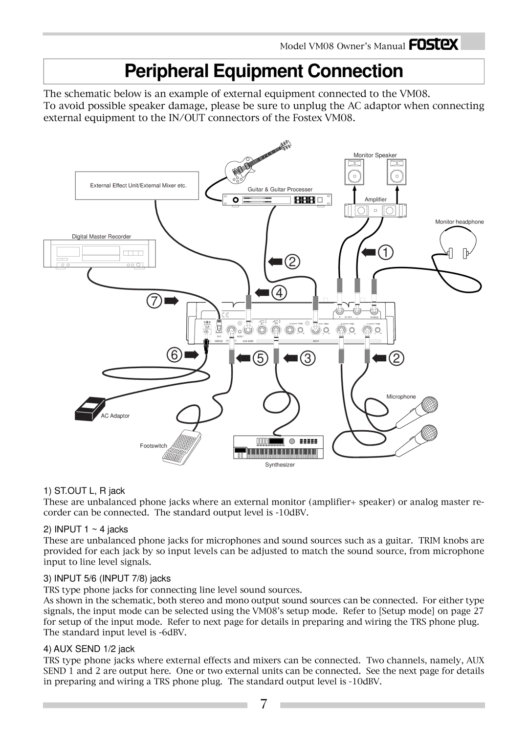
The schematic below is an example of external equipment connected to the VM08.
To avoid possible speaker damage, please be sure to unplug the AC adaptor when connecting external equipment to the IN/OUT connectors of the Fostex VM08.
External Effect Unit/External Mixer etc.
Monitor Speaker
Guitar & Guitar Processer
Amplifier
Monitor headphone
Digital Master Recorder
1
|
|
|
|
|
| 2 |
|
|
|
|
|
|
|
|
|
|
7 |
|
|
| 4 |
|
|
|
|
|
|
|
|
|
|
| |
|
|
|
|
|
|
|
|
|
|
|
|
|
|
|
| |
|
|
|
|
|
|
|
|
|
|
| R | ST OUT | L |
| PHONES |
|
| 1 |
| 7 |
| 5 |
|
|
|
|
|
|
|
|
|
|
|
9V | 2 | 8/7 | 8 | 6/5 | 6 | 4 | TRIM | TRIM | 2 | TRIM | 1 | TRIM | ||||
|
|
|
|
|
|
|
|
|
|
|
|
|
|
|
| |
ONLY |
|
|
|
|
|
|
|
|
|
|
|
|
|
|
|
|
|
|
|
|
|
|
|
|
| ||||||||
OUT | RESET |
|
|
|
|
|
|
|
|
|
|
|
|
|
|
|
DC IN DIGITAL FOOT SW | AUX SEND |
| INPUT |
6 | 5 | 3 | 2 |
Microphone
AC Adaptor
Footswitch
Synthesizer
1) ST.OUT L, R jack
These are unbalanced phone jacks where an external monitor (amplifier+ speaker) or analog master re- corder can be connected. The standard output level is
2) INPUT 1 ~ 4 jacks
These are unbalanced phone jacks for microphones and sound sources such as a guitar. TRIM knobs are provided for each jack by so input levels can be adjusted to match the sound source, from microphone input to line level signals.
3) INPUT 5/6 (INPUT 7/8) jacks
TRS type phone jacks for connecting line level sound sources.
As shown in the schematic, both stereo and mono output sound sources can be connected. For either type signals, the input mode can be selected using the VM08’s setup mode. Refer to [Setup mode] on page 27 for setup of the input mode. Refer to next page for details in preparing and wiring the TRS phone plug. The standard input level is
4) AUX SEND 1/2 jack
TRS type phone jacks where external effects and mixers can be connected. Two channels, namely, AUX SEND 1 and 2 are output here. One or two external units can be connected. See the next page for details in preparing and wiring a TRS phone plug. The standard output level is
7