24G SERIES FLATBOTTOM GAS FRYERS CHAPTER 1: SERVICE PROCEDURES
| Not used | 14 NC | |
|
| ||
|
| 12 13 | NO COM RELAY |
|
| 10 11 | PROBE |
|
| 7 8 9 | 3A 2A 1A EXT POT |
|
| 3 | AC2 |
|
| 2 | AC1 |
|
| 1 |
|
6 | 5 |
|
|
MELT CYCLE DISABLE |
|
| |
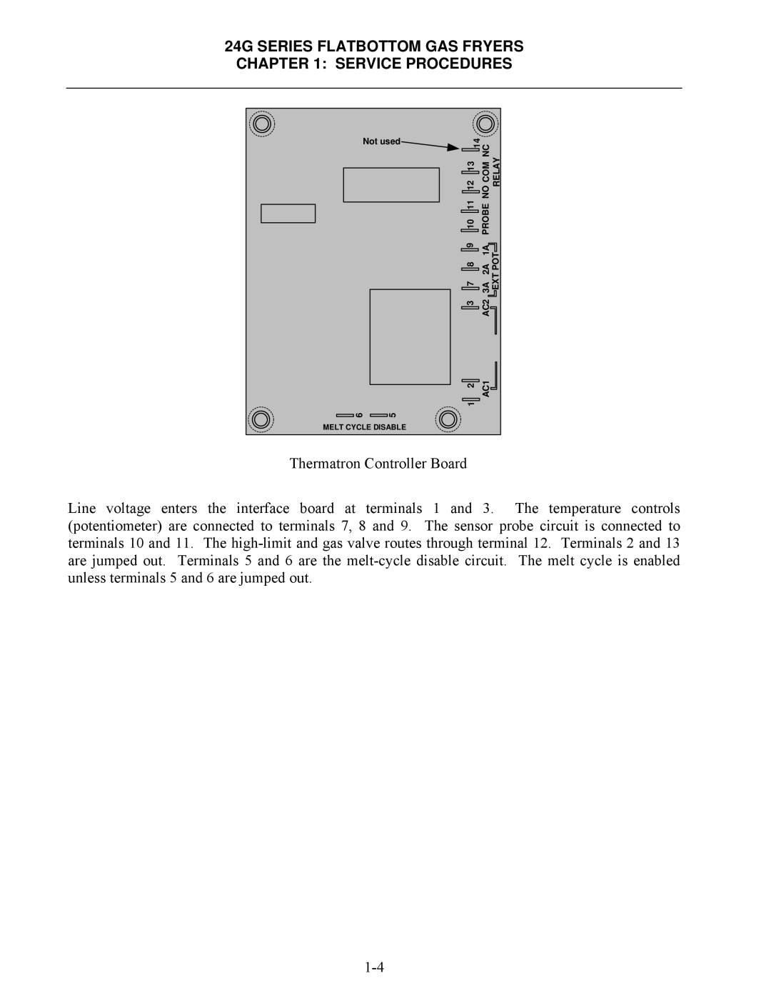
Thermatron Controller Board
Line voltage enters the interface board at terminals 1 and 3. The temperature controls (potentiometer) are connected to terminals 7, 8 and 9. The sensor probe circuit is connected to terminals 10 and 11. The