24G SERIES FLATBOTTOM GAS FRYERS CHAPTER 1: SERVICE PROCEDURES
An electromechanical gas valve regulates gas flow to the manifold. 24G Series Flatbottom gas fryers are equipped with either a
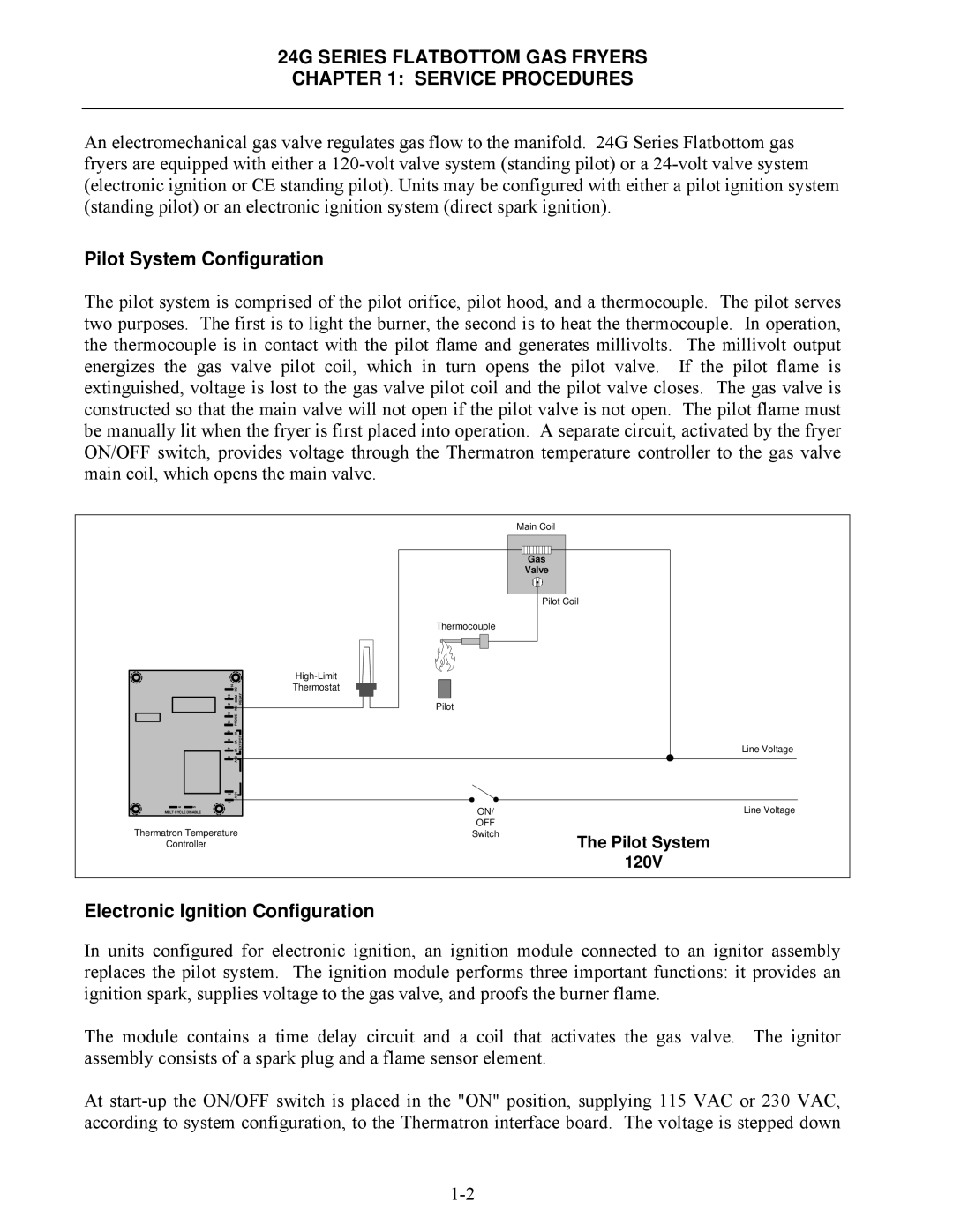
Pilot System Configuration
The pilot system is comprised of the pilot orifice, pilot hood, and a thermocouple. The pilot serves two purposes. The first is to light the burner, the second is to heat the thermocouple. In operation, the thermocouple is in contact with the pilot flame and generates millivolts. The millivolt output energizes the gas valve pilot coil, which in turn opens the pilot valve. If the pilot flame is extinguished, voltage is lost to the gas valve pilot coil and the pilot valve closes. The gas valve is constructed so that the main valve will not open if the pilot valve is not open. The pilot flame must be manually lit when the fryer is first placed into operation. A separate circuit, activated by the fryer ON/OFF switch, provides voltage through the Thermatron temperature controller to the gas valve main coil, which opens the main valve.
|
|
|
|
| Main Coil |
|
|
|
|
| Gas |
|
|
|
|
| Valve |
|
|
|
|
| Pilot Coil |
|
|
|
| Thermocouple |
|
|
|
|
|
| |
| 14 | NC | RELAY | Thermostat |
|
| 12 13 | COM | Pilot |
| |
| NO |
| |||
| 10 11 | PROBE |
|
|
|
| 9 | 1A | EXT POT |
|
|
| 7 8 | 3A 2A |
| Line Voltage | |
| 3 | AC2 |
|
|
|
| 2 | AC1 |
|
|
|
| 1 |
|
|
|
|
6 | 5 |
|
| ON/ | Line Voltage |
MELT CYCLE DISABLE |
|
| |||
Thermatron Temperature |
| OFF |
| ||
| Switch | The Pilot System | |||
Controller |
|
|
| ||
|
|
|
|
| 120V |
Electronic Ignition Configuration
In units configured for electronic ignition, an ignition module connected to an ignitor assembly replaces the pilot system. The ignition module performs three important functions: it provides an ignition spark, supplies voltage to the gas valve, and proofs the burner flame.
The module contains a time delay circuit and a coil that activates the gas valve. The ignitor assembly consists of a spark plug and a flame sensor element.
At