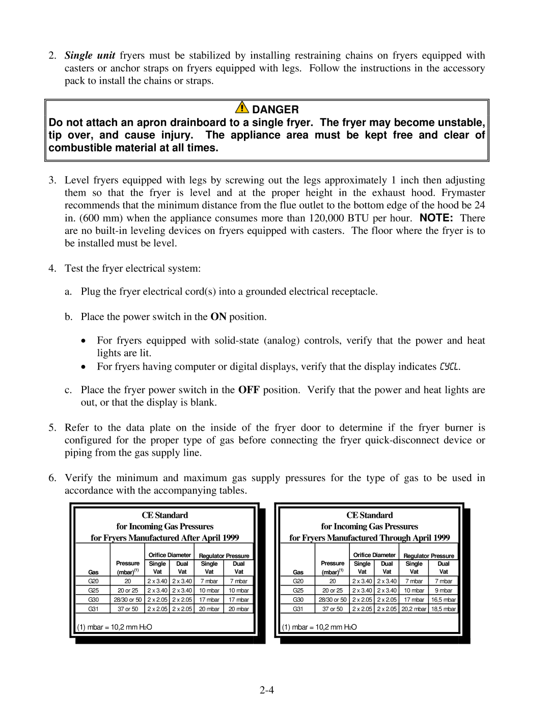
H55 specifications
The Frymaster H55 is a state-of-the-art commercial fryer that has gained acclaim in the foodservice industry for its advanced technology, efficiency, and exceptional cooking performance. Designed to meet the demanding needs of high-volume kitchens, the H55 stands out for its innovative features and user-friendly design.One of the standout elements of the Frymaster H55 is its advanced filtration system, which ensures that oil remains clean for longer periods. This not only enhances the quality of the fried food but also extends the life of the frying oil, resulting in cost savings for operators. The automatic filtration system operates seamlessly, reducing the need for manual intervention and ensuring that frying can continue uninterrupted.
Another significant feature of the H55 is its Energy Star certification, which highlights its commitment to energy efficiency. This fryer employs a unique heat transfer design that maximizes energy use while minimizing waste. By utilizing less energy to achieve the same cooking results, the Frymaster H55 helps reduce operating costs and environmental impact.
The H55 also incorporates digital technology, making it easier for chefs to monitor cooking times and temperatures precisely. With adjustable temperature controls, users can achieve consistent frying results regardless of the type of food being prepared. Additionally, the intuitive touchscreen interface allows for easy navigation, even for kitchen staff with limited experience.
The design of the Frymaster H55 allows for versatility in cooking a wide array of menu items, from crispy fried chicken to delicate fish fillets. Its ample cooking capacity ensures that high-demand items can be prepared efficiently without sacrificing quality. Moreover, the H55’s robust construction and high-quality materials contribute to its durability, ensuring it can withstand the rigors of a busy kitchen environment.
Cleanliness and safety are also key priorities for the Frymaster H55. The fryer is equipped with safety features, including over-temperature protection and a drain valve that allows for safe and efficient oil disposal. Its design facilitates quick and thorough cleaning, ensuring that health and safety standards are consistently met.
In summary, the Frymaster H55 is a cutting-edge commercial fryer that embodies efficiency, safety, and innovation. With its advanced filtration system, energy-efficient design, digital controls, and versatility, it is an essential piece of equipment for any high-volume foodservice operation, delivering exceptional frying performance while reducing operational costs.

