A-1

PLAN WIRING DIAGRAM

120V, 220V, 230V, OR 240V; 50/60 HZ., 1 Ø 3 WIRE SERVICE


INPUT 120V AC


CONTROLS


BLK

21C


WHT


22C


GRN


PRESSURE SWITCH


GROUND

120V UNITS ONLY


9C


54C


FIELD BLK


21C


CONNECTION


WHT

22C


GROUND


PILOT GENERATOR


220V, 230V, & 240V UNITS


(MILLIVOLT)


21C


TROUBLE


1

5


9


22C

14C

55C


HI-LIMIT


2

6


10


1 5


24V

3

7

T'STAT


11


4

8


12

THERMISTOR


GAS VALVE


PROBE


3C

4C


5C

1

2


10C


OIL LEVEL SWITCH ASSY


24C

25C


47C

8C


11C


9

6


5

8

3

2

12

7


24V

24V


24V


13C


INTERFACE

VALVE


12C


GAS


BOARD

C

VALVE


VALVE


24V


RELAY


66C


12VDC


36C


15P


24V


38C

26C


CONTROL


10

1

3

5

4

2

13

14


27C

COMPUTER CABLE


HEATING

7

9

10

1

3

5

4

2

13

14

ASSEMBLY


NC


NC


OFF

2

1

6

8


1

3


2

5

7

9


ON

8050402D

TO CUSTOMER PROVIDED COMPUTER

21C

22C

1 5

15

26

37

48

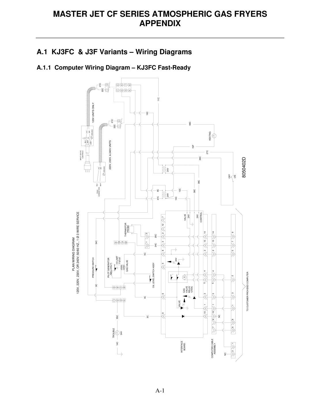
A.1.1

A.1

Computer

KJ3FC &

Wiring Diagram –

J3F Variants –

KJ3FC Fast-Ready

Wiring Diagrams

MASTER JET CF SERIES ATMOSPHERIC GAS FRYERS APPENDIX

Page 77
Image 77
Frymaster MJCFEC, FMCFEC, J65X, JCFX manual KJ3FC Fast-Ready, Plan Wiring Diagram

JCFX, J65X, J3F, KJ3FC, MJCF specifications

Frymaster, a leading manufacturer of commercial frying equipment, offers a range of fryers tailored to meet the demands of various food service operations. Among their notable products are the FMCFEC, MJCFEC, MJCF, JCFX, and FMCFE models. Each of these fryers is designed with cutting-edge technology, emphasizing efficiency, performance, and ease of use.

The FMCFEC model stands out for its advanced filtration system, which provides exceptional oil management. This feature helps extend the life of cooking oil, delivering consistent frying quality while reducing operational costs. The FMCFEC is equipped with a digital controller that simplifies temperature management, ensuring food is cooked to perfection every time.

The MJCFEC is another remarkable model in Frymaster's lineup, featuring a versatile design suited for quick-service and casual dining establishments. It boasts a compact footprint while still offering a large frying capacity, enabling operators to maximize their output in limited space. Additionally, the MJCFEC incorporates energy-efficient technology, resulting in lower utility bills and a reduced environmental impact.

The MJCF model is geared toward high-volume frying, utilizing a powerful heating system that ensures rapid oil recovery. This fryer's heavy-duty construction enhances durability, making it ideal for busy kitchens where reliability is paramount. The MJCF model also features a straightforward interface, allowing staff to operate it with minimal training.

The JCFX model is designed with flexibility in mind, allowing for customizable frying options. This fryer offers multiple frying baskets and a range of temperature settings, making it suitable for various menu items, from fries to seafood. Its user-friendly digital controls enhance operational efficiency, making it easier for kitchen staff to manage frying times and temperatures.

Lastly, the FMCFE model emphasizes energy savings and oil conservation without sacrificing performance. This fryer incorporates advanced technology to monitor oil quality and usage, allowing operators to optimize their frying processes. The FMCFE's design focuses on safety, with features that minimize the risk of burns and splatters in busy kitchen environments.

In summary, Frymaster’s FMCFEC, MJCFEC, MJCF, JCFX, and FMCFE models reflect the company's commitment to innovation and quality in commercial frying equipment. With their distinctive features, energy efficiency, and user-friendly designs, these fryers are well-suited for a variety of food service applications, providing operators with reliable performance and exceptional results.