5. INSTALLATION
This chapter provides the procedures neces- sary for installation. Installation mainly con- sists of the following:
Ásiting and mounting the display unit and antenna unit
Áconnection of the signal cable and the power cable
Áestablishing the ground
Áchecking the installation, and
Áadjustments.
5.1 Antenna Unit Installation
Siting, handling considerations
ÁThe antenna unit is generally installed either on top of the wheelhouse or on the radar mast on a suitable platform. Locate the antenna unit where there is a good
ÁIt is rarely possible to place the antenna unit where a completely clear view in all direc- tion is available. Thus, you should determine the angular width and relative bearing of any shadow sectors for their influence on the ra- dar at the first opportunity after fitting. (The method of determining blind and shadow sectors appears later in this chapter.)
ÁIf you have a radio direction finder on your boat, local its antenna clear of the antenna unit, to prevent interference to the direction finder. A separation of more than two meters is recommended.
ÁTo lessen the chance of picking up electrical interference, avoid where possible routing the signal cable near other onboard electri- cal equipment. Also avoid running the cable in parallel with power cables.
ÁThe compass safe distance should be ob- served to prevent deviation of the magnetic compass.
Standard compass | Steering compass |
|
|
0.9 m | 0.7 m |
|
|
ÁDo not paint the radome to ensure proper emission of the radar waves.
ÁWhen this radar is to be installed on larger vessels, consider the following points:
(1)The signal cable run between the antenna and the display comes in lengths of 10 m, 15 m, 20 m and 30 m. Whatever length is used it must be unbroken; namely, no splicing allowed.
(2)Deposits and fumes from a funnel or other exhaust vent can adversely affect the aerial performance and hot gases may distort the radiator portion. The an-
tenna unit must not be mounted where the temperature is more than 70°C.
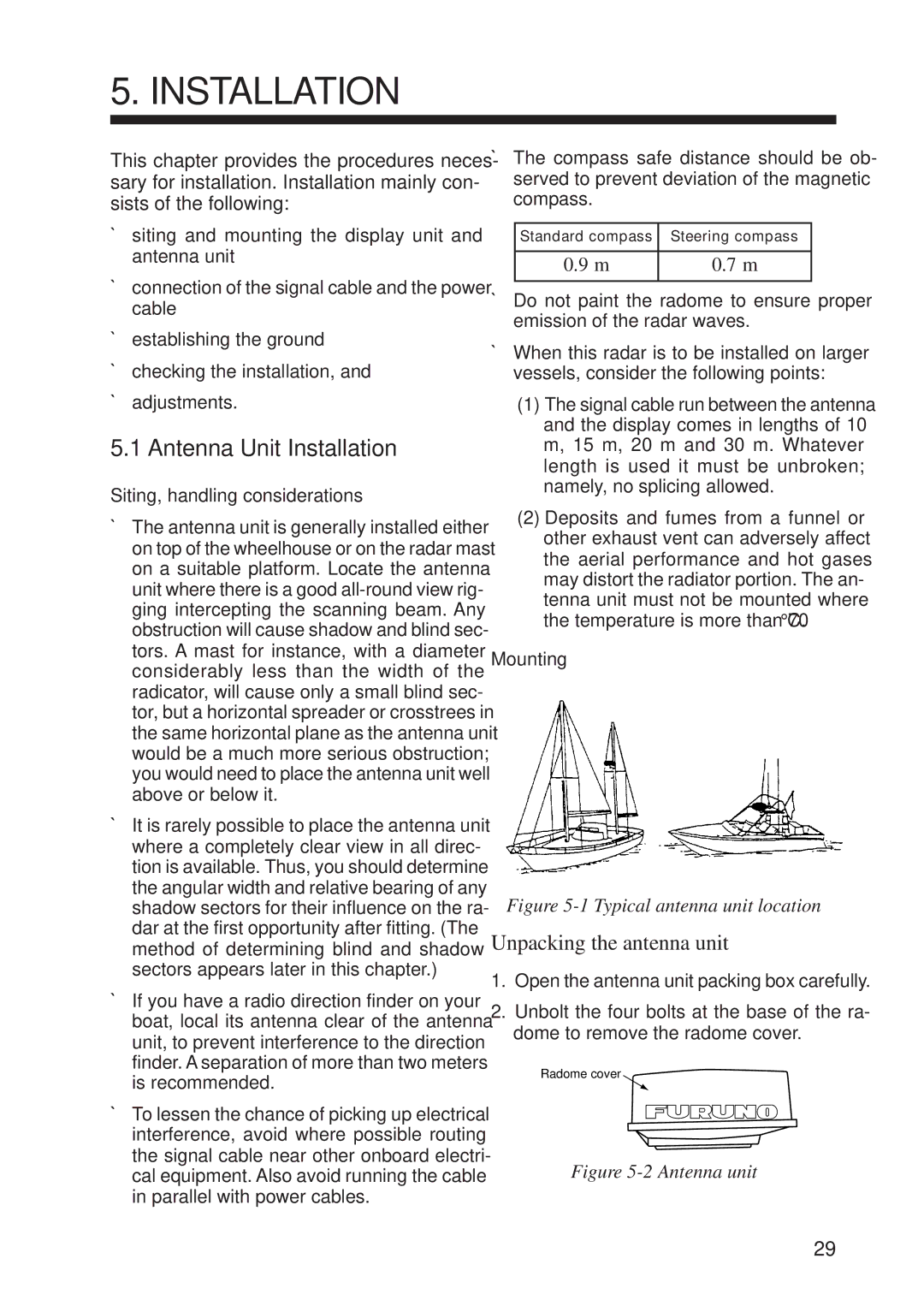
Mounting
Figure 5-1 Typical antenna unit location
Unpacking the antenna unit
1.Open the antenna unit packing box carefully.
2.Unbolt the four bolts at the base of the ra- dome to remove the radome cover.
Radome cover
Figure 5-2 Antenna unit
29