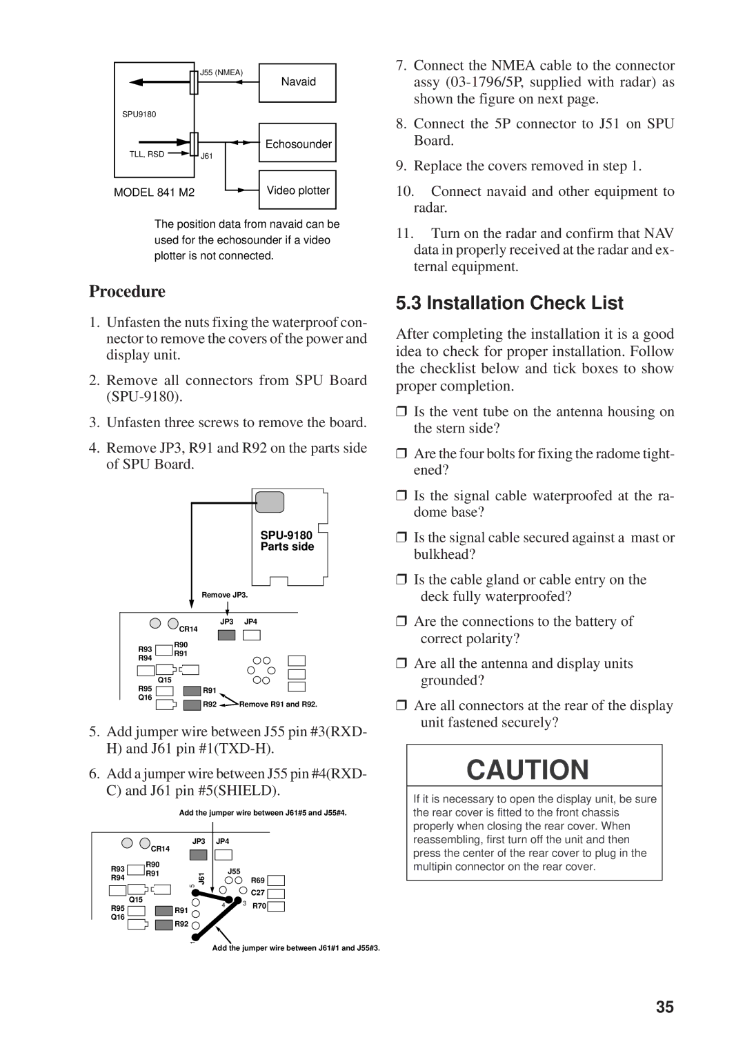
| J55 (NMEA) |
SPU9180 |
|
TLL, RSD | J61 |
MODEL 841 M2 |
|
Navaid
Echosounder
Video plotter
7. | Connect the NMEA cable to the connector |
| assy |
| shown the figure on next page. |
8. | Connect the 5P connector to J51 on SPU |
| Board. |
9. | Replace the covers removed in step 1. |
10. Connect navaid and other equipment to | |
| radar. |
The position data from navaid can be used for the echosounder if a video plotter is not connected.
11. Turn on the radar and confirm that NAV |
data in properly received at the radar and ex- |
ternal equipment. |
Procedure
1.Unfasten the nuts fixing the waterproof con- nector to remove the covers of the power and display unit.
2.Remove all connectors from SPU Board
3.Unfasten three screws to remove the board.
4.Remove JP3, R91 and R92 on the parts side of SPU Board.
5.3 Installation Check List
After completing the installation it is a good idea to check for proper installation. Follow the checklist below and tick boxes to show proper completion.
❒ Is the vent tube on the antenna housing on |
the stern side? |
❒ Are the four bolts for fixing the radome tight- |
ened? |
❒ Is the signal cable waterproofed at the ra- |
dome base? |
R93
R94
Parts side
Remove JP3.
JP3 JP4
CR14
R90
R91
❒ Is the signal cable secured against a mast or |
bulkhead? |
❒ Is the cable gland or cable entry on the |
deck fully waterproofed? |
❒ Are the connections to the battery of |
correct polarity? |
❒ Are all the antenna and display units |
R95 | Q15 |
|
|
| |||||
|
|
| |||||||
|
|
|
|
| R91 |
|
|
| |
|
|
|
|
|
|
|
| ||
Q16 |
|
|
|
|
| R92 | Remove R91 and R92. | ||
|
|
|
|
|
| ||||
|
|
|
|
|
|
|
|
|
|
5.Add jumper wire between J55 pin #3(RXD-
H)and J61 pin
6.Add a jumper wire between J55 pin #4(RXD-
C)and J61 pin #5(SHIELD).
Add the jumper wire between J61#5 and J55#4.
| JP3 | JP4 |
|
| |
| CR14 |
|
|
|
|
R93 | R90 |
| J55 |
|
|
R91 | J61 |
|
| ||
R94 |
| R69 | |||
5 |
|
| |||
|
|
|
| ||
|
|
|
|
| |
| Q15 |
|
|
| C27 |
R95 |
| 4 | 3 | R70 | |
R91 |
| ||||
|
|
|
| ||
Q16 | R92 |
|
|
|
|
|
|
|
|
| |
| 1 |
|
|
|
|
Add the jumper wire between J61#1 and J55#3.
grounded? |
❒ Are all connectors at the rear of the display |
unit fastened securely? |
CAUTION
If it is necessary to open the display unit, be sure the rear cover is fitted to the front chassis properly when closing the rear cover. When reassembling, first turn off the unit and then press the center of the rear cover to plug in the multipin connector on the rear cover.
35