2. WIRING
*2:The following cables are optionally supplied for heading sensor connection.
Type | Code no. | Remarks |
|
(5m) | |||
(10m) |
*3:The following cables can be used for NMEA 0183 format connection.
Type | Code no. | Remarks |
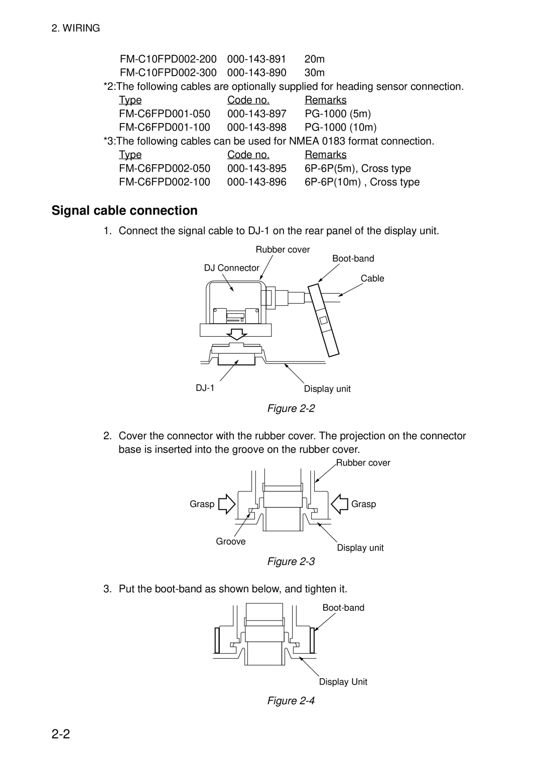
Signal cable connection
1. Connect the signal cable to
Rubber cover
DJ Connector
Cable
Display unit |
Figure
2.Cover the connector with the rubber cover. The projection on the connector base is inserted into the groove on the rubber cover.
Rubber cover
Grasp
Groove
Grasp
Display unit
Figure
3.Put the
![]()
Display Unit
Figure
