2. WIRING
2.1 Connection
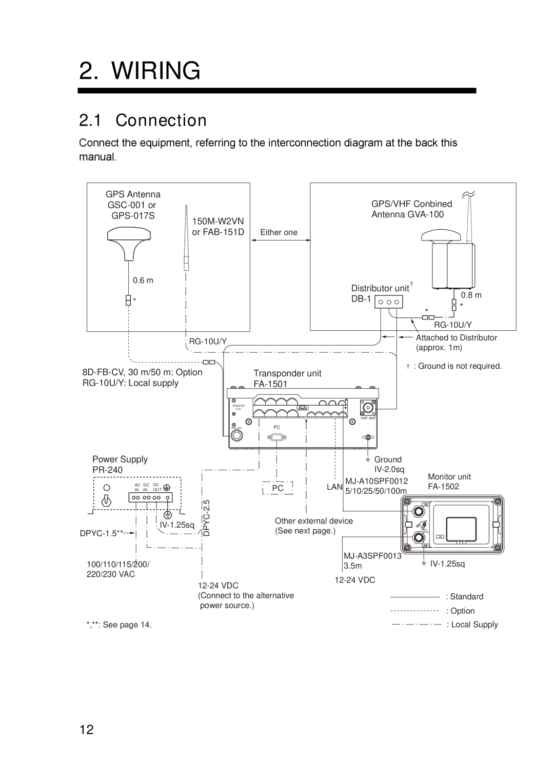
Connect the equipment, referring to the interconnection diagram at the back this manual.
GPS Antenna
0.6 m
![]()
![]() *
*
| GPS/VHF Conbined |
Antenna | |
| |
or |
|
Distributor unit |
| 0.8 m |
| ||
| * | |
| * | |
|
| |
|
|
|
|
|
|
| Attached to Distributor | |||||
|
|
|
| |||||||
|
|
|
|
| (approx. 1m) | |||||
|
|
|
|
|
|
|
|
|
| |
|
|
|
|
|
|
|
|
|
| : Ground is not required. |
|
|
|
|
|
|
|
|
|
| |
Transponder unit |
| |||||||||
| ||||||||||
Power Supply
AC DC DC
IN IN OUT
![]()
100/110/115/200/ 220/230 VAC
*,**: See page 14.
BREAKER |
|
|
|
|
6.3A |
|
|
|
|
|
|
| VHF ANT |
|
GPS ANT | PC |
|
|
|
|
|
| Ground |
|
|
|
| Monitor unit | |
|
|
| ||
| PC | LAN | ||
|
|
| 5/10/25/50/100m |
|
|
|
|
| |
DPYC | Other external device |
| ||
(See next page.) |
|
| ||
|
| ||||
| 3.5m |
| |||
|
|
| |||
|
|
|
|
| |
(Connect to the alternative |
|
|
|
| : Standard |
|
|
|
| ||
power source.) |
|
|
|
| : Option |
|
|
|
|
| |
: Local Supply
12