3. INSTALLATION
Terminal resistor
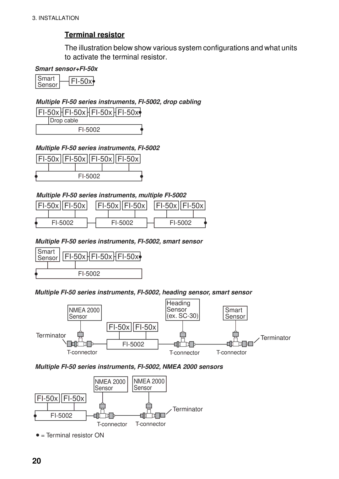
The illustration below show various system configurations and what units to activate the terminal resistor.
Smart
Smart |
|
|
| ||
Sensor |
| |
|
|
Multiple
![]()
![]()
![]()
![]()
![]()
![]()
Drop cable
Multiple
![]()
![]()
![]()
![]()
![]()
![]()
Multiple
![]()
![]()
![]()
![]()
![]()
![]()
Multiple
Smart
Sensor FI-50x FI-50x FI-50x
Multiple
NMEA 2000 Sensor
Heading
Sensor
(ex.
Smart Sensor
|
| ||
Terminator |
|
| Terminator |
| |||
|
| ||
| |||
Multiple
NMEA 2000
Sensor
![]()
![]()
![]() = Terminal resistor ON
= Terminal resistor ON
NMEA 2000
Sensor
Terminator
20
