Drill bit for:
Bracket holes: 4 mm, #23, or 9/64"
Fiberglass hull: chamfer bit (preferred), 6 mm, or 1/4"
Transom hole: 19 mm or 3/4" (optional)
Cable clamp holes: 3 mm or 1/8" Screwdrivers
Straight edge Marine sealant Pencil
Mounting location
To ensure the best performance, the sensor must be submerged in
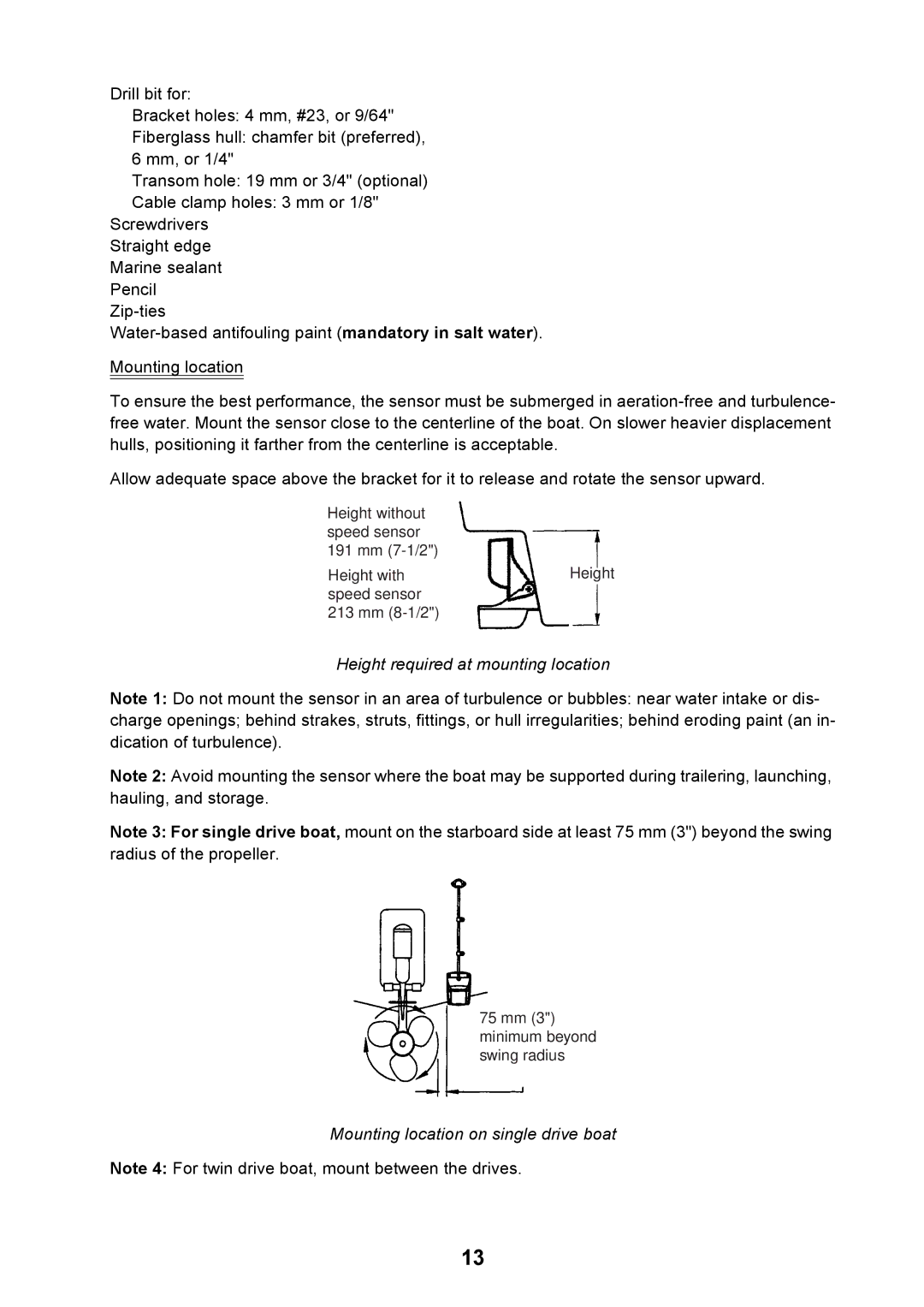
Allow adequate space above the bracket for it to release and rotate the sensor upward.
Height without speed sensor 191 mm
Height with | Height |
speed sensor |
|
213 mm |
|
Height required at mounting location
Note 1: Do not mount the sensor in an area of turbulence or bubbles: near water intake or dis- charge openings; behind strakes, struts, fittings, or hull irregularities; behind eroding paint (an in- dication of turbulence).
Note 2: Avoid mounting the sensor where the boat may be supported during trailering, launching, hauling, and storage.
Note 3: For single drive boat, mount on the starboard side at least 75 mm (3") beyond the swing radius of the propeller.
75 mm (3") minimum beyond swing radius
Mounting location on single drive boat
Note 4: For twin drive boat, mount between the drives.
13