Magnum
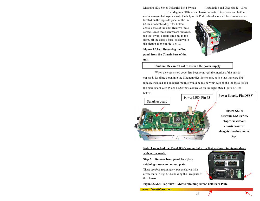
The Magnum
(2 each on both side), 8 for bottom chassis base of the unit. Remove these screws. Once these screws are removed, the
Figure 3.6.1a: Removing the Top panel from the Chassis base of the unit
Caution: Be careful not to disturb the power supply.
When the chassis top cover has been removed, the interior of the unit is exposed. Looking down into the Magnum
below.
Daughter board
Power LED, Pin J5
Power Supply, Pin DSSV
Figure 3.6.1b:
Magnum
Top view without chassis cover w/ daughter module on the top.
Note:
Step 3. Remove front panel face plate retaining screws and screen plate
There are four retaining screws as shown with arrow mark in Fig 3.6.1c holding the face plate of the chassis.
Figure 3.6.1c: Top View – 6KPM retaining screws hold Face Plate
www . GarrettCom . com
33