CHAPTER 2 - Installation
Installation of the DX40 Unit
2.3.1.2Mounting in a DIN Rail System
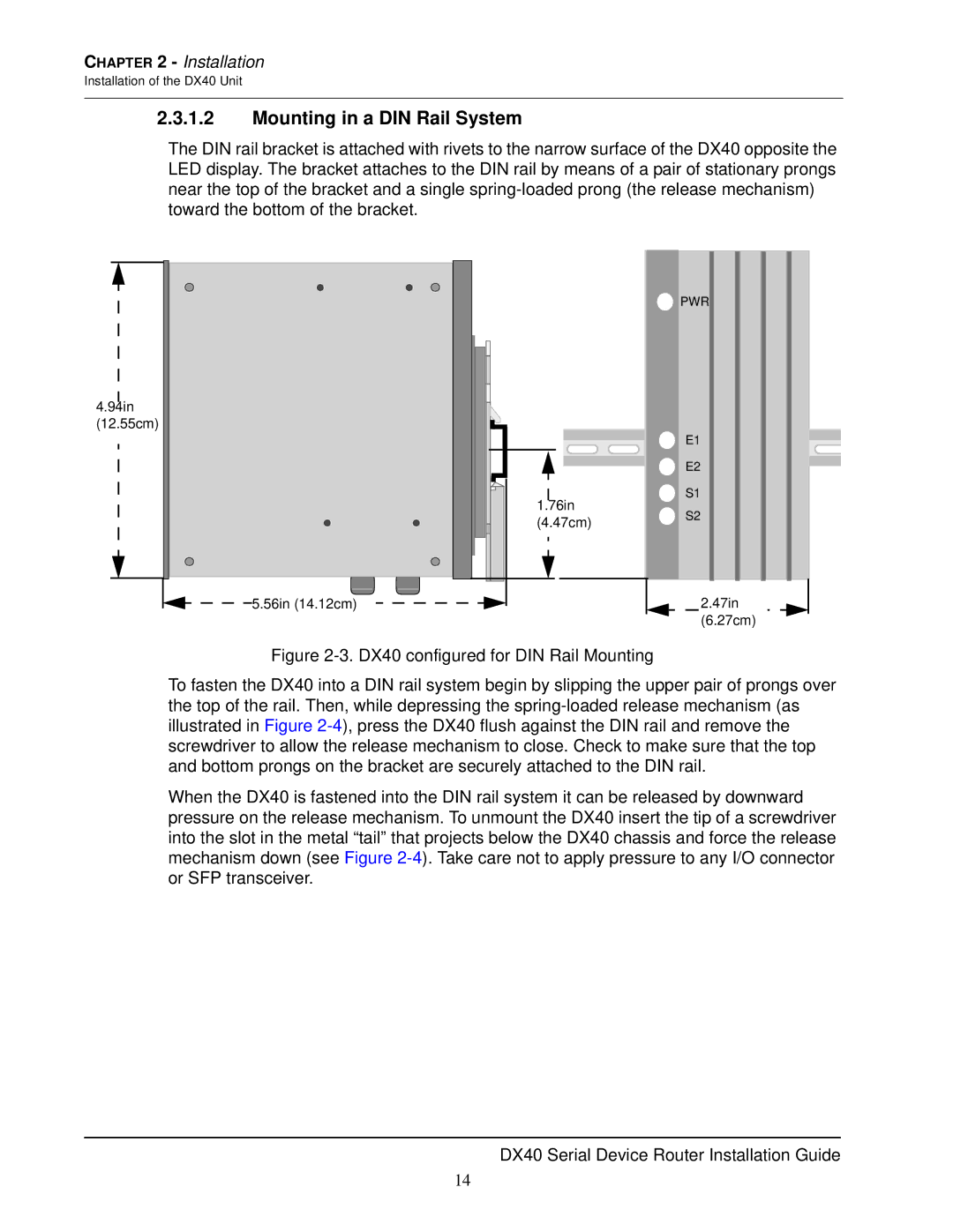
The DIN rail bracket is attached with rivets to the narrow surface of the DX40 opposite the LED display. The bracket attaches to the DIN rail by means of a pair of stationary prongs near the top of the bracket and a single
4.94in
(12.55cm)
5.56in (14.12cm)
1.76in |
(4.47cm) |
PWR |
E1 |
E2 |
S1 |
S2 |
2.47in |
(6.27cm) |
Figure 2-3. DX40 configured for DIN Rail Mounting
To fasten the DX40 into a DIN rail system begin by slipping the upper pair of prongs over the top of the rail. Then, while depressing the spring-loaded release mechanism (as illustrated in Figure 2-4), press the DX40 flush against the DIN rail and remove the screwdriver to allow the release mechanism to close. Check to make sure that the top and bottom prongs on the bracket are securely attached to the DIN rail.
When the DX40 is fastened into the DIN rail system it can be released by downward pressure on the release mechanism. To unmount the DX40 insert the tip of a screwdriver into the slot in the metal “tail” that projects below the DX40 chassis and force the release mechanism down (see Figure 2-4). Take care not to apply pressure to any I/O connector or SFP transceiver.
DX40 Serial Device Router Installation Guide
14