CHAPTER 2 - Installation
Installation of the DX40 Unit
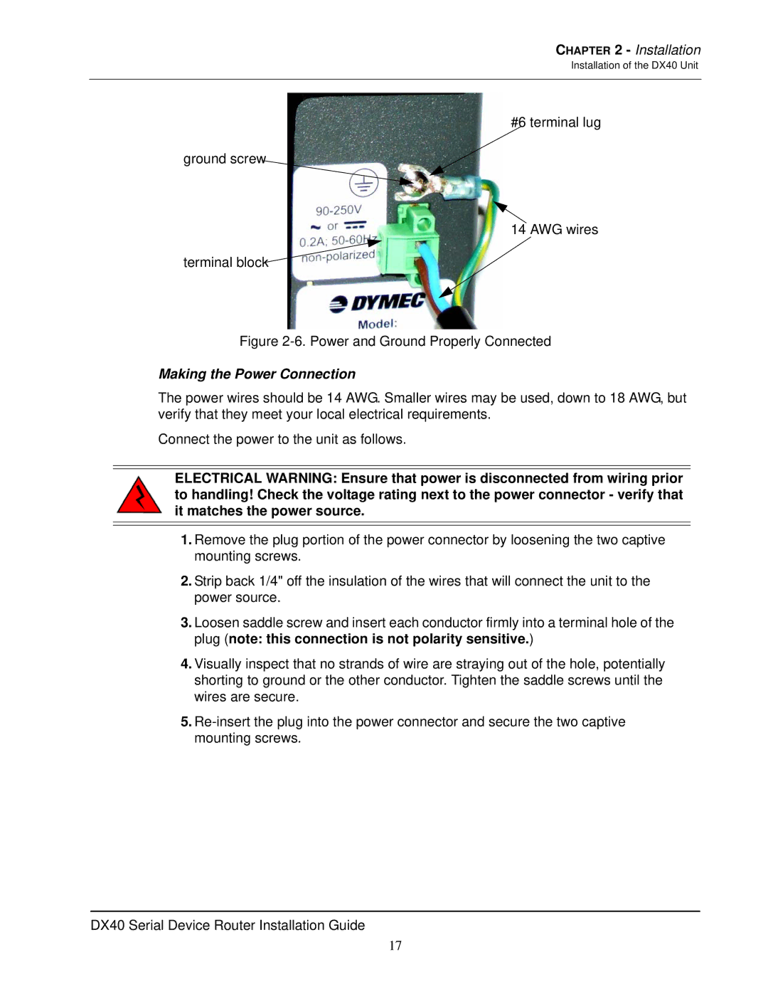
#6 terminal lug
ground screw
14 AWG wires
terminal block
Figure 2-6. Power and Ground Properly Connected
Making the Power Connection
The power wires should be 14 AWG. Smaller wires may be used, down to 18 AWG, but verify that they meet your local electrical requirements.
Connect the power to the unit as follows.
ELECTRICAL WARNING: Ensure that power is disconnected from wiring prior to handling! Check the voltage rating next to the power connector - verify that it matches the power source.
1.Remove the plug portion of the power connector by loosening the two captive mounting screws.
2.Strip back 1/4" off the insulation of the wires that will connect the unit to the power source.
3.Loosen saddle screw and insert each conductor firmly into a terminal hole of the plug (note: this connection is not polarity sensitive.)
4.Visually inspect that no strands of wire are straying out of the hole, potentially shorting to ground or the other conductor. Tighten the saddle screws until the wires are secure.
5.
DX40 Serial Device Router Installation Guide
17