CHAPTER 1 - Overview
Pinouts
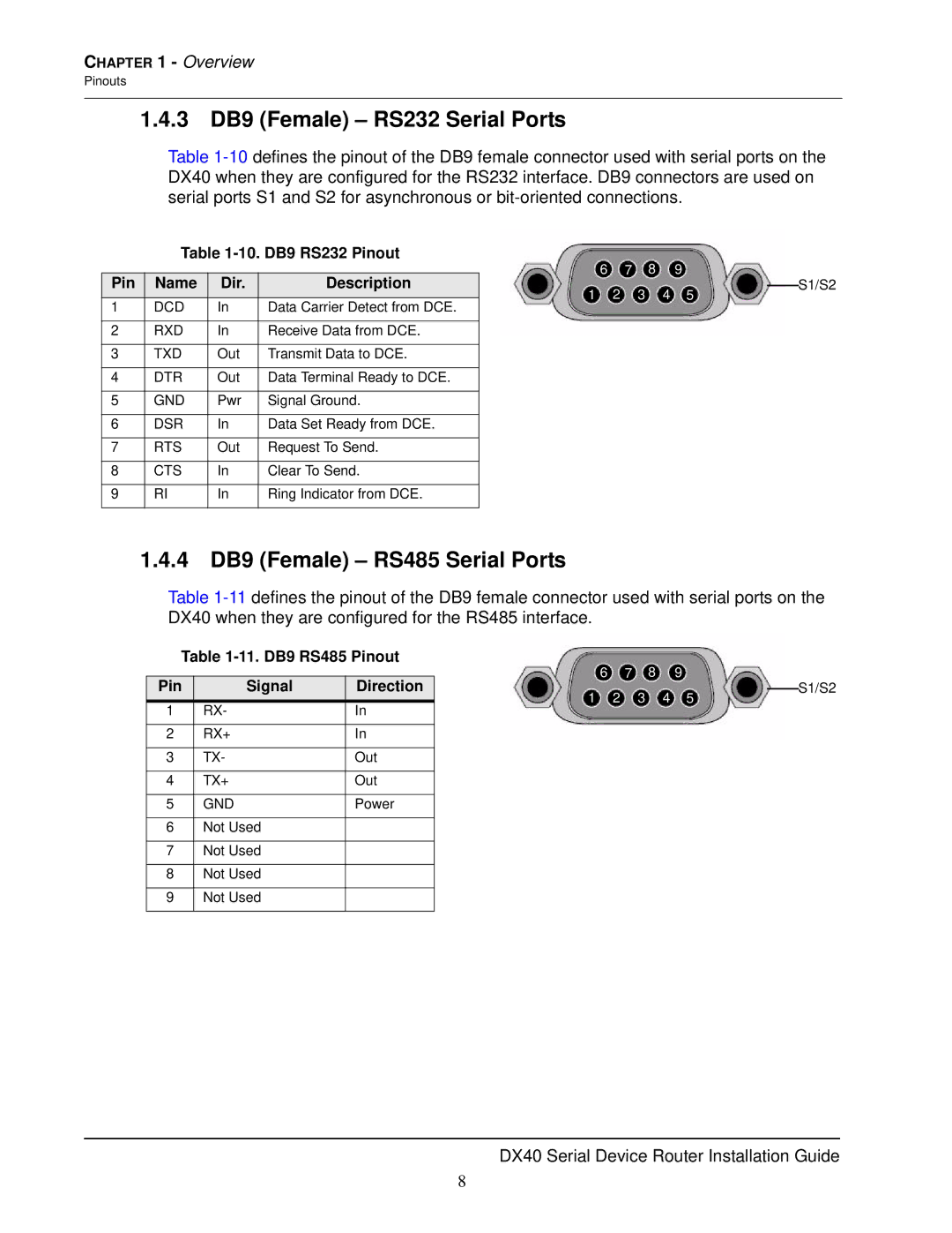
1.4.3 DB9 (Female) – RS232 Serial Ports
Table
Table 1-10. DB9 RS232 Pinout
|
|
|
| 6 | 7 | 8 |
| 9 |
|
|
Pin | Name | Dir. | Description |
|
| S1/S2S | ||||
1 | 2 | 3 | 4 | 5 |
| |||||
| ||||||||||
1 | DCD | In | Data Carrier Detect from DCE. |
|
| |||||
|
|
|
|
|
|
| ||||
|
|
|
|
|
|
|
|
|
|
|
2 | RXD | In | Receive Data from DCE. |
|
|
|
|
|
|
|
|
|
|
|
|
|
|
|
|
|
|
3 | TXD | Out | Transmit Data to DCE. |
|
|
|
|
|
|
|
|
|
|
|
|
|
|
|
|
|
|
4 | DTR | Out | Data Terminal Ready to DCE. |
|
|
|
|
|
|
|
|
|
|
|
|
|
|
|
|
|
|
5 | GND | Pwr | Signal Ground. |
|
|
|
|
|
|
|
|
|
|
|
|
|
|
|
|
|
|
6 | DSR | In | Data Set Ready from DCE. |
|
|
|
|
|
|
|
|
|
|
|
|
|
|
|
|
|
|
7 | RTS | Out | Request To Send. |
|
|
|
|
|
|
|
|
|
|
|
|
|
|
|
|
|
|
8 | CTS | In | Clear To Send. |
|
|
|
|
|
|
|
|
|
|
|
|
|
|
|
|
|
|
9 | RI | In | Ring Indicator from DCE. |
|
|
|
|
|
|
|
|
|
|
|
|
|
|
|
|
|
|
1.4.4 DB9 (Female) – RS485 Serial Ports
Table
Table 1-11. DB9 RS485 Pinout
|
|
| 6 | 7 | 8 |
| 9 |
|
|
Pin | Signal | Direction |
|
| S1/S2S | ||||
1 | 2 | 3 | 4 | 5 |
| ||||
| |||||||||
1 | RX- | In |
|
| |||||
|
|
|
|
|
|
| |||
|
|
|
|
|
|
|
|
|
|
2 | RX+ | In |
|
|
|
|
|
|
|
|
|
|
|
|
|
|
|
|
|
3 | TX- | Out |
|
|
|
|
|
|
|
|
|
|
|
|
|
|
|
|
|
4 | TX+ | Out |
|
|
|
|
|
|
|
|
|
|
|
|
|
|
|
|
|
5 | GND | Power |
|
|
|
|
|
|
|
|
|
|
|
|
|
|
|
|
|
6 | Not Used |
|
|
|
|
|
|
|
|
|
|
|
|
|
|
|
|
|
|
7 | Not Used |
|
|
|
|
|
|
|
|
|
|
|
|
|
|
|
|
|
|
8 | Not Used |
|
|
|
|
|
|
|
|
|
|
|
|
|
|
|
|
|
|
9 | Not Used |
|
|
|
|
|
|
|
|
|
|
|
|
|
|
|
|
|
|
DX40 Serial Device Router Installation Guide
8