g
GE
CAUTION !
Panel “E” should never be removed or replaced with power applied to the UPS. This panel is in close proximity to 480V live buss bars.
Always disconnect the rectifier, bypass, load and battery sources from the UPS before removing or replacing this panel.
If not serious injury or death could occur!
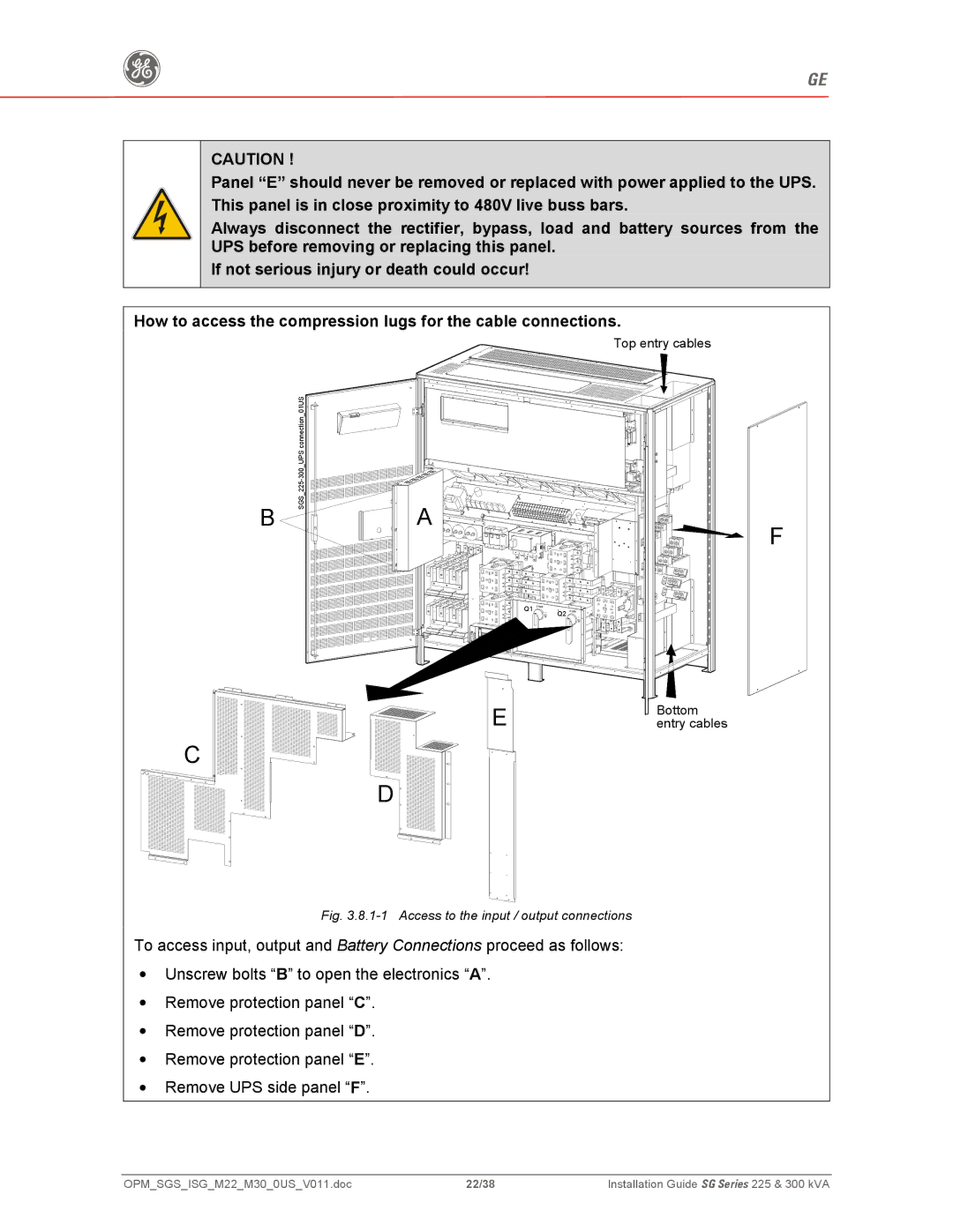
How to access the compression lugs for the cable connections.
Top entry cables
| connection 01US |
| 300 UPS |
| 225- |
B | SGS_ |
|
C![]()
![]()
![]()
![]()
![]() A
A
Q1
E
D
Q2
F
Bottom entry cables
Fig. 3.8.1-1 Access to the input / output connections
To access input, output and Battery Connections proceed as follows:
•Unscrew bolts “B” to open the electronics “A”.
•Remove protection panel “C”.
•Remove protection panel “D”.
•Remove protection panel “E”.
•Remove UPS side panel “F”.
OPM_SGS_ISG_M22_M30_0US_V011.doc | 22/38 | Installation Guide SG Series 225 & 300 kVA |