g
GE
4.1.3Programmable input free contacts
Some programmable UPS functions (indicated in section 4.1), can be activated by closing an external contact, if connected, on:
X1 / 10, 21 | or | J2 / 10, 23 | User Input 1 | (default = Not used) | (RL1) |
X1 / 11, 22 | or | J2 / 11, 24 | User Input 2 | (default = Emergency GEN ON) | (RL2) |
4.1.4Gen Set Signaling (GEN ON)
If an emergency generator set supplies the UPS in case of Utility Failure and the generator is particularly unstable in frequency, it should be suitable to install the signal “Generator ON” on X1/11, 22 or J2/11, 24 (this input is programmed as default for this function).
When this contact closes, it causes the change of certain functions (programmable) such as:
•Enabling or disabling of synchronization and consequently the Load transfer to generator.
•Reduction or elimination or delay of Battery recharging during the generator operation.
In a parallel system a separate NO (Normally Open) contact must be connected individually to each unit.
4.1.5AUX external Maintenance Bypass
If the UPS system is equipped with an external Maintenance Bypass Switch, it is possible to connect a NO (normally open) voltage free aux. contact from the External Bypass Switch to the programmable input
This function can be activated by changing a dedicated parameter (password required).
When this NO (Normally Open) contact closes, the output Inverter Contactor K7 it is automatically opened and the Load transfer back to Inverter will be inhibited.
In a parallel system, the input on customer interface of each unit must be connected to a separate AUX contact of the External Maintenance Bypass Switch.
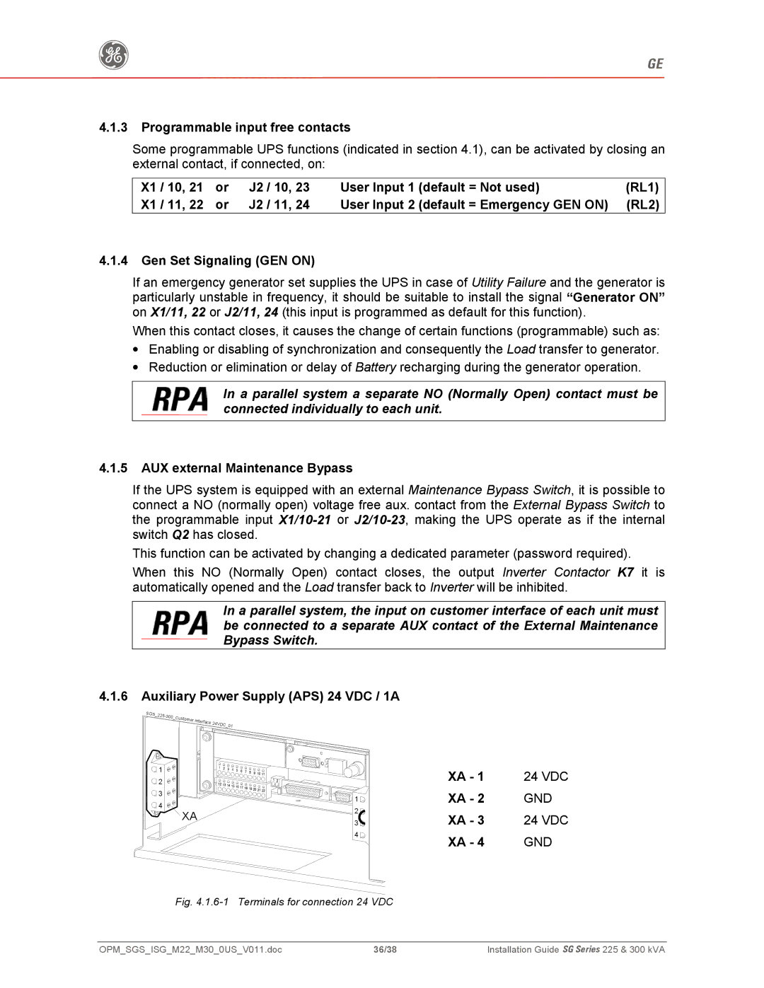
4.1.6Auxiliary Power Supply (APS) 24 VDC / 1A
1 |
|
| |
2 |
|
| |
3 |
| 1 | |
4 |
| ||
XA | 2 | ||
| |||
| 3 | ||
|
| ||
|
| 4 |
XA - 1 | 24 VDC |
XA - 2 | GND |
XA - 3 | 24 VDC |
XA - 4 | GND |
Fig. 4.1.6-1 Terminals for connection 24 VDC
OPM_SGS_ISG_M22_M30_0US_V011.doc | 36/38 | Installation Guide SG Series 225 & 300 kVA |