SG Series
Copyright 2003 by GE Industrial Systems
Systems
Dear Customer
Start UP and Commissioning
Preface
Table of contents
Installation
Battery
General
Storage
Safety instructions when working with battery
Safety symbols and warnings
Safety warnings
Risk of electric shock PE Earth GND Ground
Protective Grounding Terminal
Layout
Layout SG Series 225 and 300 KVA
Dimensions and weight
Weight SG Series 225 and 300 kVA
Transport Forklift Crane
Transport UPS only in upright position
Storage of the UPS
Storage of Battery
Delivery
Check -26A of the NEC code for specific requirements
Place of Installation
Positioning of the UPS SG Series
Openings for input and output cable connections
Fixing of the UPS cabinet on the floor
Battery location
1-5 RPA system disposition
Ventilation and Cooling
CFM
Packing material recycling
Take care not to damage the UPS when moving by forklift
Unpacking
Common input Rectifier & Bypass
Electrical Wiring
Separate input Rectifier & Bypass recommended
Input/output over current protection and wire sizing
Neutral current could be greater than the phase currents
Phase, 3 wire plus Ground
Phase, 4 wire plus Ground
Wire positive and negative plus Ground
See .7.1-1
Copper
Wiring Connection
Wire Size Range
1-1 Access to the input / output connections
Output Load
Power connection with common input utility
Common Input Rectifier / Bypass
Cable section for this connection shall be not less then AWG
Power connection separate input utility
L1-1 Rectifier Phase a L1-2
L2-1 Rectifier Phase B L2-2
L3-1 Rectifier Phase C L3-2
BR1
Battery connection
Battery
Positive pole of the Battery
Do not insert the Battery Fuses before the commissioning
Setup for SG Series when functioning as frequency converter
Manual Bypass, serious damage to the Load could result
Power Wiring of Parallel Units
1 RPA Parallel System
UPS
Parallel Control BUS Connection
Terminal units
Intermediate units
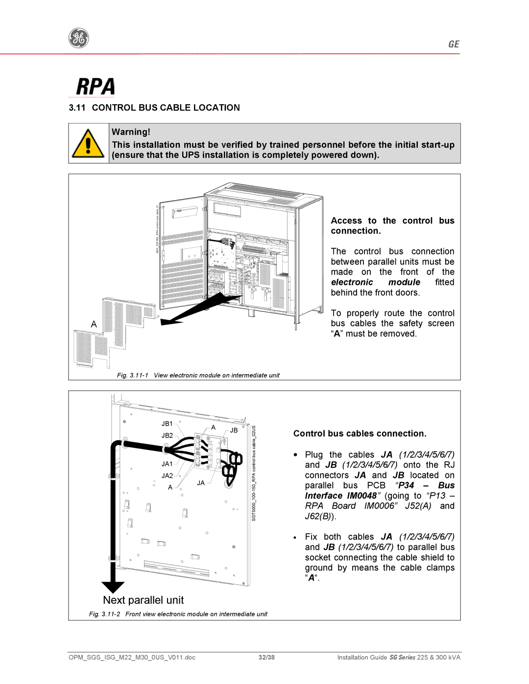
Access to the control bus connection
Control BUS Cable Location
Control bus cables connection
Interface IM0048 going to P13
Control bus cables routing
11-3 Control Bus cable routing and connection
Customer Interface
Customer Interface
15, 16 Or J2 17, 18 NO, C, NC General Alarm
18, 19 Or J2 20, 21 NO, C, NC Acoustic Alarm
Output potential free contacts
Or J2 / 1, 2 NO, C, NC Utility Failure
GND
EPO Emergency Power Off Input contact
JP3
38/38