Installation Instructions

INSTALL THE RANGE

3ANTI-TIP DEVICE INSTALLATION

WARNING:

Range must be secured with an approved Anti-Tip device.

Unless properly installed, the range could be tipped by you or a child standing, sitting or Ieaning on an open door.

After installing the Anti-Tip device, verify that it is in place by carefully attempting to tilt the range forward.

This range has been designed to meet all recognized ¡ndustry tip standards for alI normal conditions.

After installing the Anti-Tip device, verify that it is in place by carefully attempting to tilt the range forward:

The use of this device does not preclude tipping of the range when not properly instaIIed.

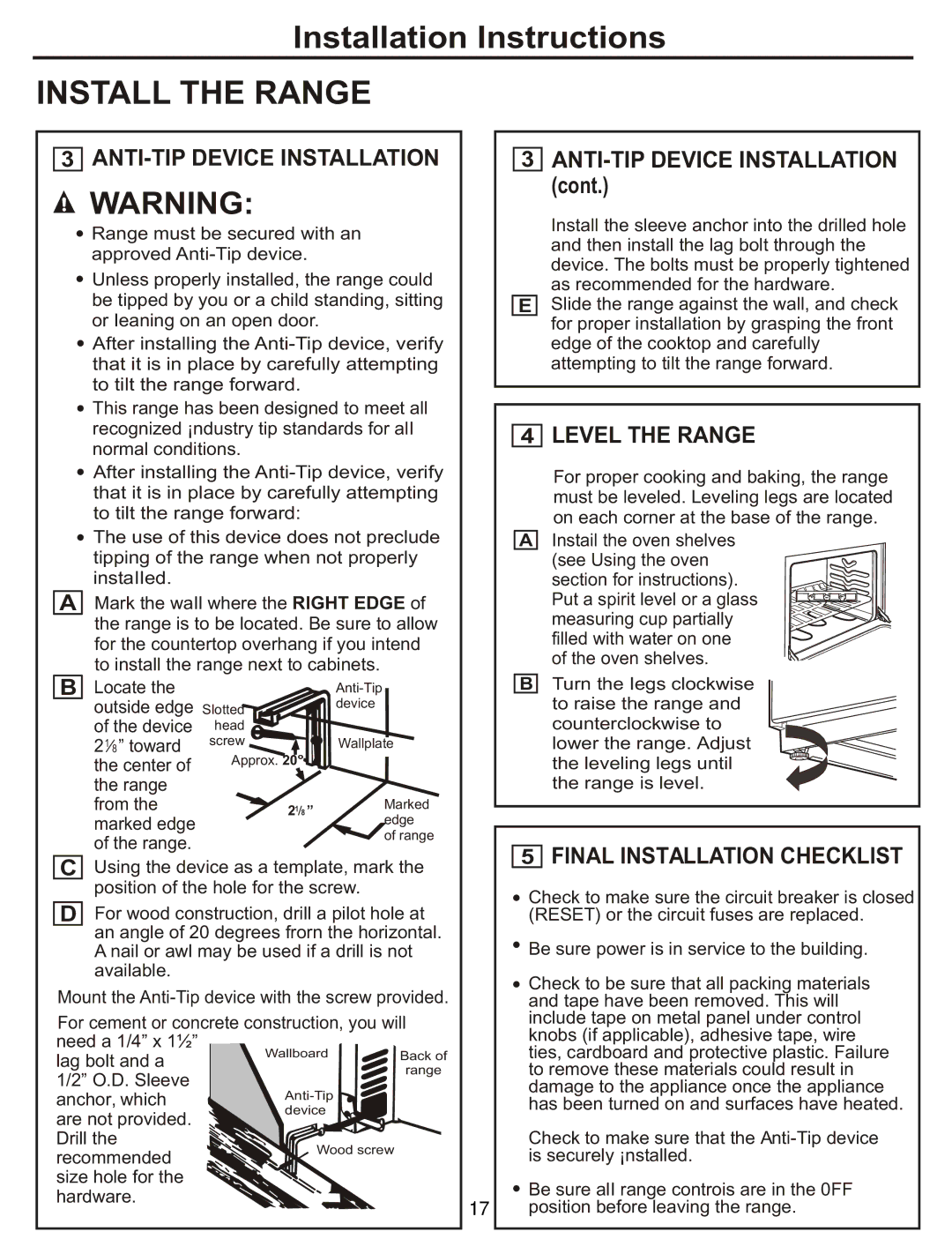
AMark the waIl where the RIGHT EDGE of the range is to be located. Be sure to allow for the countertop overhang if you intend to install the range next to cabinets.

B

Locate the


Anti-Tip


outside edge Slotted

device


of the device

head


21 8 ” toward

screw

Wallplate

the center of

Approx. 20°


the range


from the

21 8

Marked

marked edge


edge

of the range.


of range


CUsing the device as a template, mark the position of the hole for the screw.

DFor wood construction, drill a pilot hole at an angle of 20 degrees frorn the horizontal. A nail or awl may be used if a drill is not available.

Mount the Anti-Tip device with the screw provided.

For cement or concrete construction, you will

need a 1/4” x 1½”

Wallboard

Back of

lag bolt and a


1/2” O.D. Sleeve


range

Anti-Tip


anchor, which


are not provided.

device


Drill the

Wood screw


recommended


size hole for the


hardware.


17


3ANTI-TIP DEVICE INSTALLATION (cont.)

Install the sleeve anchor into the drilled hole and then install the lag bolt through the device. The bolts must be properly tightened as recommended for the hardware.

ESlide the range against the wall, and check for proper installation by grasping the front edge of the cooktop and carefully attempting to tilt the range forward.

4LEVEL THE RANGE

For proper cooking and baking, the range must be leveled. Leveling legs are located on each corner at the base of the range.

AInstail the oven shelves

(see Using the oven section for instructions). Put a spirit level or a glass measuring cup partially filled with water on one of the oven shelves.

BTurn the Iegs clockwise

to raise the range and counterclockwise to lower the range. Adjust the leveling legs until the range is level.

5FINAL INSTALLATION CHECKLIST

Check to make sure the circuit breaker is closed (RESET) or the circuit fuses are replaced.

Be sure power is in service to the building.

Check to be sure that all packing materials and tape have been removed. This will include tape on metal panel under control knobs (if applicable), adhesive tape, wire ties, cardboard and protective plastic. Failure to remove these materials could result in damage to the appliance once the appliance has been turned on and surfaces have heated.

Check to make sure that the Anti-Tip device is securely ¡nstalled.

Be sure alI range controis are in the 0FF position before leaving the range.

Page 17
Image 17
GE JCAS 730 manual Install the Range

JCAS 730 specifications

The GE JCAS 730 is an advanced jet engine specifically designed for modern commercial aircraft. Renowned for its efficiency and reliability, the JCAS 730 is a product of General Electric's extensive expertise in aerospace technology, catering to the growing demand for greener and more economical aviation solutions.

One of the main features of the GE JCAS 730 is its high bypass ratio, which significantly enhances fuel efficiency. The engine’s design allows for a larger volume of air to bypass the core engine, reducing the overall fuel consumption while maintaining optimal thrust levels. This characteristic makes the JCAS 730 an ideal choice for airlines focused on lowering operational costs and minimizing their carbon footprint.

Incorporating the latest in materials technology, the GE JCAS 730 utilizes carbon fiber reinforced polymers and high-temperature superalloys in its construction. These lightweight materials contribute to the engine's performance by reducing weight and improving thermal efficiency. The innovative design also aids in improving the longevity of the engine components, leading to lower maintenance costs and extended intervals between overhauls.

The JCAS 730 is equipped with state-of-the-art digital engine control systems, allowing for precise monitoring and management of engine performance. This digital architecture not only optimizes thrust during various flight phases but also enhances safety through real-time data analysis. Operators can access vital information that assists in predictive maintenance, further enhancing reliability and operational efficiency.

Another distinguishing feature of the GE JCAS 730 is its noise-reduction technology. The engine is designed with advanced acoustic liners and chevron nozzles that significantly decrease noise levels during takeoff and landing. This capability not only helps airlines comply with increasingly stringent noise regulations but also contributes to community acceptance of airport operations.

Furthermore, the JCAS 730 integrates seamlessly with advanced aircraft systems, providing pilots with enhanced situational awareness. Its compatibility with modern avionics ensures that airlines can adapt to future technological advancements without the need for major overhauls.

In conclusion, the GE JCAS 730 stands out in the competitive landscape of aviation engines due to its high efficiency, cutting-edge materials, smart digital controls, and noise-reduction capabilities. With its commitment to sustainability and performance, the JCAS 730 is positioned to meet the needs of a rapidly evolving aviation industry while setting new standards for jet engine technology.