MM300 specifications
The GE MM300 is a robust and versatile controller designed primarily for industrial automation applications. Built to tackle the demands of modern manufacturing environments, this controller offers a range of features that contribute to its popularity among engineers and operators.One of the standout features of the GE MM300 is its scalability. The device can be easily configured to meet the needs of both small and large systems. Its modular architecture allows users to add or remove components based on the specific requirements of their applications, facilitating a more tailored approach to automation.
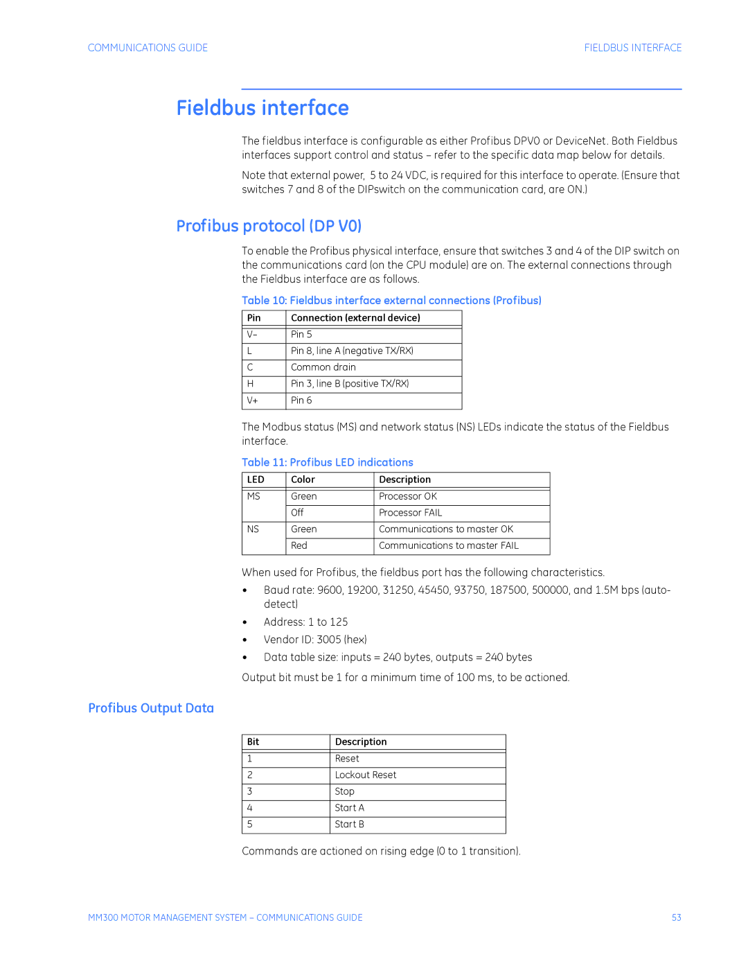
The MM300 supports various communication protocols, including Ethernet/IP, Modbus TCP, and more, ensuring seamless integration with a variety of devices and systems. This feature significantly enhances interoperability, allowing users to connect the controller to existing infrastructure without extensive reconfiguration.
In terms of processing power, the MM300 is equipped with a high-performance processor that can handle complex tasks with ease. With advanced data handling capabilities, it supports real-time data processing, enabling faster decision-making and improving overall operational efficiency. This capability is particularly beneficial for applications requiring precise control and monitoring.
Moreover, the GE MM300 boasts a user-friendly interface, featuring an intuitive programming environment that simplifies the development of control applications. This includes an integrated development environment (IDE) and support for popular programming languages, making it accessible for both seasoned programmers and those new to automation technologies.
The device is designed to operate in challenging industrial conditions, featuring a rugged construction that ensures durability and longevity. Its ability to withstand extreme temperatures, vibrations, and other environmental stressors enhances its reliability in demanding applications, which is crucial for minimizing downtime in production processes.
Security is another critical aspect of the GE MM300. The controller incorporates advanced security features to protect against unauthorized access and cyber threats, helping organizations ensure the integrity of their operations.
In summary, the GE MM300 stands out due to its scalability, versatile communication options, high processing capabilities, user-friendly programming environment, rugged design, and security features. These characteristics make it a reliable choice for industries seeking to enhance their automation processes and improve overall efficiency. Whether for small-scale or large-scale applications, the MM300 provides a comprehensive solution to meet the evolving needs of modern manufacturing.
