Profile
Exhaust/Ducting
Clear the room, building or area of all occupants
California Safe Drinking Water and Toxic Enforcement Act
Ge.com
Your Laundry Area
When not Using Your Dryer
About the dryer control panel
Power
Quick Start
Cycle Knob
Sensor Dry Level
Dry Cycles
Timed Dry
To store a MY Cycle combination of settings
Clean Lint Filter message
Dry Temp
Display
Washer Communicated Cycles
Specialty Cycles
Specialty Cycles include Garments
Bed and Bath
About cycle options
Settings
About dryer features
Drum Lamp
Built-in Rack Dry System with TumbleCare Baffles
To Use the Built-In Hook for Hanging Garments
Reverse Tumble
Care and Cleaning of the Dryer
Using the dryer
Sorting and Loading Hints
Fabric Care Labels
DPVH880 and UPVH880
For Your Safety
Before YOU Begin
For GAS Models only
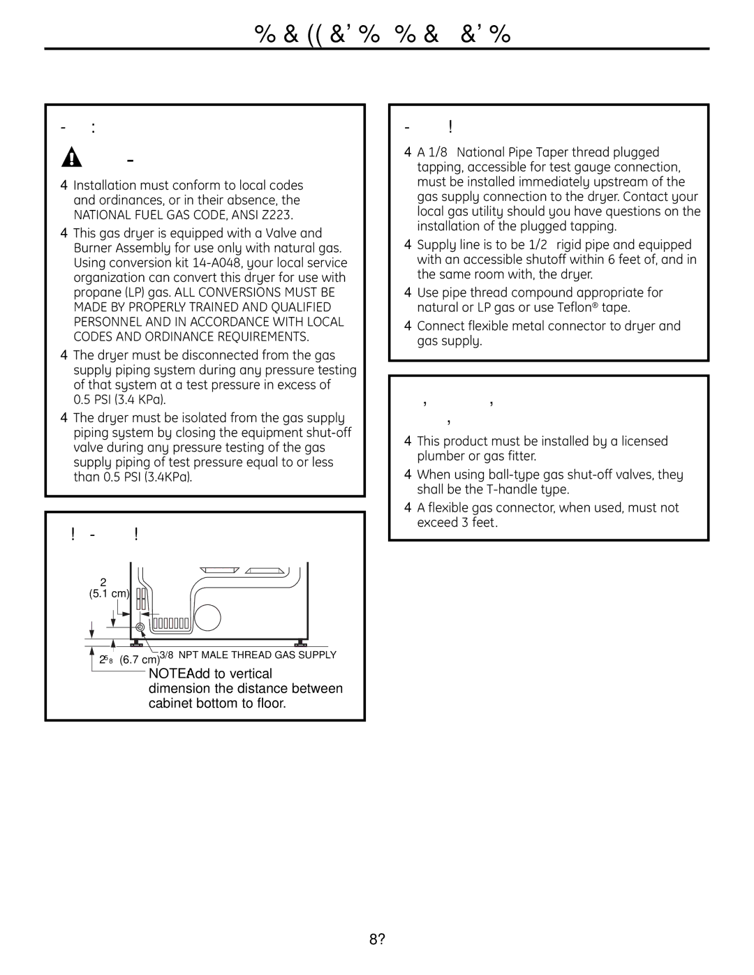
Dryer Dimensions
Installation Instructions
Minimum Clearance Other than Alcove or Closet Installation
Unpacking Your Dryer
Mobile or Manufactured Home Installation
Bathroom or Bedroom Installation
Installation must conform to
Dryer Must be vented to the outdoors. See
Tools YOU will Need
Materials YOU will Need For Your Safety
Dryer GAS Supply Connection
GAS Requirements
GAS Supply
Commonwealth Massachusetts
Connecting the Dryer To the GAS Supply
Installation Instructions Connecting a GAS Dryer
Connecting the Dryer
Attach the flexible metal gas line connector to the adapter
Electrical Requirements For GAS Dryers
Test for Leaks
Electrical Connection Information for GAS Dryers
Ensure proper ground exists before use
Electrical Connection Information for Electric Dryers
″ duct clamps 2 or ″ spring clamps Safety glasses
Flat-blade screwdriver Level
Gloves Exhaust hood Duct tape
Grounding Instructions
Electrical Requirements For Electric Dryers
Connecting Dryer Using 3-WIRE Connection
Installation Instructions Connecting AN Electric Dryer
Tools and Materials YOU will Need to Install Exhaust Duct
Exhaust System Checklist
Using Flexible Metal Duct for Transition Venting
Installation Instructions Exhausting the Dryer
Do not
For Transition Venting Dryer to WALL, do
USE only Metal Duct 4″ Diameter 102 mm
Example only
Equivalent
Duct Pieces
Caps
Number
Length
Using duct elbows will prevent duct kinking and collapsing
Recommended Configuration to Minimize Exhaust Blockage
Standard Rear Exhaust
Remove any lint from the wall exhaust opening
TAB Location
Side Venting
Adding a NEW Duct
To Wear Gloves
Back Opening Without the Plate
Adding Cover Plate to Rear of Cabinet Side Exhaust
Reconnect the cut
Bottom Venting
Portion a Duct to the blower
Bottom opening
Adding Cover Plate to Rear of Cabinet Bottom Exhaust
Bottom Venting
Plug Dryer
Level the Dryer
Attach Serial Cable
Servicing
Press the Power button Dryer is now ready for use
Dryer Startup
Standard Reversibility KIT
Important Notes
To the left and right
Chrome door cap Chrome door hinge cap Inner door cap
Door Parts
Before YOU Start
Remove the Door Assembly
Unplug the dryer from its electrical outlet
Remove the side hinge cap by opening
Reverse Door Handle and Caps
Reverse Door Handle and Caps
Assemble the new right-side door cap
Reverse Hinge and Caps
Reverse Front Panel Plug Buttons and Strike Plate
Reassemble Door Assembly
Reinstall Door Assembly
Before YOU Begin
Install Rubber Pads to Dryer Base
KIT Contents
Installation Preparation
Install Dryer and Bracket on Washer
Install Bracket to Dryer
Finalize the Installation
Set the dryer upright
Support pads Drawer divider Mounting screws
Remove the Leveling Legs
Phillips head
Screwdriver
Prepare the Pedestal
Install the Pedestal To the Washer or Dryer
Pull the drawer out as far as it Will go
Slides. Slide drawer out of the base and set aside
Level the Washer or Dryer
Reinstall the Drawer
Remove Shipping Screws
Check to Be sure the slides are closed Slide the drawer
Possible Causes What To Do
Before you call for service…
Replace both fuses or reset both breakers. Your dryer
Power button was activated
Time Remaining
This is normal
Procedures before drying
When washed. Others can be
Clothes shrink
To avoid shrinkage, follow garment care labels exactly
Warrantor General Electric Company. Louisville, KY
Safety Instructions For The Period Of We Will Replace
What Is Not Covered in the United States
For The Period
What Is Not Covered in Canada
We Will Replace
Modèle N Série N
Conduit d’évacuation
Qualifié, une entreprise de réparation
Autour DE Votre Sécheuse
Conservez CES Directives
Cycle
Power alimentation
Démarrage
Dry Cycles cycles de séchage
Propos du panneau de contrôle de la sécheuse
Timed Dry séchage minuté
Sensor Dry Level détection du niveau d’humidité
Display affichage
Dry Temp température de séchage
Cycles reliés à la laveuse
Specialty Cycles cycles spéciaux
Literie et salle de bain
Autres articles spéciaux
Damp Alert Alerte dhumidité
Options de cycle
Drum Light Lumière du tambour
Lock Verrouillage
Propos des caractéristiques de la sécheuse
Settings Réglage
Lumière de tambour
Appuyez sur la touche Drying Rack Grille DE Séchage
Reverse TumbleMC
Grille de séchage accessoire en option
Étiquettes d’entretien de tissu
Utilisation de la sécheuse
Étiquettes de séchage
Entretien et nettoyage
Avant DE Commencer
DPVH880 et UPVH880
Pour Votre Sécurité
Pour LES Modèles À GAZ Uniquement
Dimensions DE LA Sécheuse
Instructions d’installation
Déballage DE Votre Sécheuse
Vue avant
Installation Dans UNE Maison Mobile OU Préfabriquée
Exigences Relatives UNE Installation Encastrée
Installation Dans UNE Salle DE Bain OU UNE Chambre
M2 120 po carrés
Matériel Nécessaire Pour Votre Sécurité
Outils Nécessaires
Alimentation EN GAZ
Exigences Relatives AU GAZ
Dans LE Commonwealth DU Massachusetts
Raccordement DE L’ALIMENTATION EN GAZ DE LA Sécheuse
Raccordement DE LA Sécheuse À L’ALIMENTATION EN GAZ
Installez un raccord adaptateur à l’obturateur
Raccordement DE LA Sécheuse À L’ALIMENTATION EN GAZ Suite
De l’adaptateur et de l’obturateur
Avertissement Cette
Avertissement N’utilisez
Détection DES Fuites
La procédure de détection de fuites
Lunettes de protection Tuyau métallique
Tournevis à tête plate Niveau
Si nécessaire Gants ’event d’évacuation Ruban adhésif
La prise murale de votre domicile avant d’acheter le cordon
Instructions DE Mise À LA Terre
Utiliser Pour L’INSTALLATION Dans UNE Maison Mobile
Branchement DE LA Sécheuse À L’AIDE D’UN Câble À 4 Fils
NE Laissez Jamais LE Couvercle Enlevé
NE Laissez Jamais LE Couvercle Enlevé DE LA Plaque À Bornes
Raccordement DE LA Sécheuse À L’AIDE D’UN Câble À 3 Fils
Évent Mural
Avertissement Pour
Séparations DES Coudes
Étanchéité DES Joints
NE Faites PAS
Instructions d’installation Évacuation DE LA Sécheuse suite
Coupez
’ÉCRASEZ PAS
Longueur
Exemple Uniquement
Conduits
Tableau D’ÉQUIVALENCE DES Conduits
Nombre
De ruban en toile
Évacuation Arrière Standard
Enlevez toute charpie de l’ouverture d’évacuation murale
Avant DE Procéder À L’INSTALLATION
Emplacement DE LA Languette
Évacuation Latérale
Ajouter UN Nouveau Conduit
DE LA SÉCHEUSE. Ensemble WE1M454
La sécheuse à son emplacement final
Ajouter UNE Plaque D’OBTURATION
Évacuation PAR LE Dessous
Avant DE Procéder a L’INSTALLATION
DE Gants
’intérieur de la sécheuse lors de l’insertion du conduit
Connectez les coudes et les conduits
Son emplacement final
Branchement DU Câble Série
Mettez LA Sécheuse DE Niveau
Branchez LA Sécheuse
Et de l’avant vers l‘arrière
Une installation/réparation
Maintenance
De téléphone du service après-vente
Démarrage DE LA Sécheuse
Toutes les vis doivent être vissées à la main
Remarques Importantes
Ensemble D’INVERSION Standard
Couvre-charnière Couvercle de porte chromé
Pièces DE LA Porte
#8 x 0,375 po
11 #8 x 0,625 po
Comment Démonter LA Porte
Comment Retirer LA Porte
Débranchez la sécheuse de sa prise électrique
Sur une surface plane, lisse et protégée
Comment Inverser LA Poignée ET LES Couvercles DE LA Porte
Vis taraudeuses #8 x 0,75 po
Comment Inverser LA Charnière ET LES Couvercles
Mastic ou un tournevis à fine lame
Comment Réinstaller LA Porte
Comment Réinstaller LA Porte
Comment Inverser
LES Capuchons ET LA Gâche DU Panneau Avant
Comment Superposer LA Sécheuse À LA Laveuse optionnel
Tournevis cruciforme Gants Clé à fourche
Contenu DE L’ENSEMBLE
Comment Installer LA Sécheuse ET LE Support SUR LA Laveuse
Comment Installer LE Support SUR LA Sécheuse
Avertissement Blessure
Ne pas masquer le panneau de contrôle de la laveuse
Comment Préparer L’INSTALLATION
Instructions d’installation Installation DU Socle optionnel
’INSTALLATION Doit Être Effectuée PAR Deux Personnes
Contenu D’ENSEMBLE
Pour LES Sécheuses Uniquement
Comment Installer LE Socle SUR LA Laveuse OU LA Sécheuse
Comment Préparer LE Socle
Comment Terminer L’INSTALLATION
Comment Réinstaller LE Tiroir
Comment Mettre LA Laveuse OU LA Sécheuse DE Niveau
Régler les pieds. Vissez l’écrou de blocage au bas du socle
Problème Causes possibles Correctifs
Avant d’appeler un réparateur…
Mais 00 est le temps
La sécheuse émet Temperature ou l’OPTION Un double bip
Restant n’est pas affiché. L’option de culbutage
Chauffe lorsque l’alimentation en gaz est restaurée
Afin qu’ils retrouvent leur forme d’origine
’autres peuvent être lavés
Dans la sécheuse
La machine ou ne le séchez pas dans la sécheuse
Pour une période de Nous remplacerons
Garantie de la sécheuse GE
Ce qui n’est pas couvert
Conseils de
Prolongation de garantie
Soutien au consommateur Service de réparations
Modelo # Serie #
De este o cualquier otro artefacto
Vapores o líquidos inflamables cerca
Salida al exterior/Conductos
Agencia de servicio o el proveedor de gas
De funcionamiento
SU Área DE Lavadero
Guarde Estas Instrucciones
Sobre el panel de control de la secadora
Power encendido
Inicio rápido
El botón START/PAUSE
Sensor Dry Level nivel de secado con sensor
Dry Cycles ciclos de secado
Timed Dry secado temporizado
Dry Temp temperatura de secado
Clean Lint Filter message limpiar filtro de pelusas mensaje
START/PAUSE inicio/pausa
My Cycle mi ciclo en algunos modelos
Ciclos con comunicación con la lavadora
Specialty Cycles ciclos especiales
Los ciclos especiales Specialty Cycles incluyen Prendas
Cama y baño
Sobre las opciones de ciclo
Delay Start inicio retardado
Damp Alert alerta de humedad
Drum Light luz del tambor
Sobre las características de la secadora
Settings configuraciones
Lámpara del tambor
LOW
Secado reverso
Secado por tendedero accesorio opcional
Cómo usar el gancho incorporado para colgar prendas
Consejos de clasificación y carga
Cómo usar la secadora
Etiquetas sobre cuidado
De las telas
Antes DE Comenzar
DPVH880 y UPVH880
Para SU Seguridad
Sólo Para Modelos a GAS
Instrucciones de instalación
Dimensiones DE LA Secadora
Cómo Desempacar LA Secadora
Saque la bolsa que contiene la información y cable serial
Instalación EN Casas Móviles Prefabricadas
Instalación EN Baños Dormitorios
Requerimientos Para Instalación EN Nichos O Armarios
El material del conducto de ventilación
Materiales Necesarios Para SU Seguridad
Herramientas Necesarias
Conexión DE Suministro DE GAS DE LA Secadora
Requerimientos DE GAS
Suministro DE GAS
EN LA Mancomunidad DE Massachusetts
Cierre la válvula de apagado del gas
Cómo Conectar LA Secadora AL Suministro DE GAS
Conexión Eléctrica Información Sobre LAS Secadoras a GAS
Prueba DE Pérdidas
Utilice una llama abierta para detectar pérdidas de gas
Requerimientos Eléctricos Para Secadoras a GAS
Destornillador de lados
Si se cuenta con una secadora a gas, saltear este paso
Planos
Clasificado UL De 120/240V, 30A con
Requerimientos Eléctricos Para Secadoras Eléctricas
122
Campana O Cubierta DE Pared
Lista DE Control DEL Sistema DE Salida
Separación DE Curvas
Sellado DE Juntas
No Haga LO Siguiente
Sólo UN Ejemplo
Paredes INTERNAS/CIELORRASO
Tabla DE Equivalencia DE Componentes DE LOS Conductos
Recomendamos instalar la secadora antes
Salida Trasera Estándar
Quite las pelusas de la abertura de salida de la pared
Ubicación DE LA Lengüeta
Ventilación Lateral
Cómo Agregar UN Conducto Nuevo
Corte el conducto como puede verse y conserve la porción a
SIN LA Placa EN SU LUGAR. Kit WE1M454
Nunca Deje LA Abertura Trasera
La secadora cuando introduzca el conducto
Gire el codo a través de La abertura inferior
Quite la tapa inferior
De seguridad
Del tornillo de la porción a donde se conecta con el codo
Conecte EL Cable Serial
Nivele LA Secadora
Enchufe LA Secadora
Instrucciones DE Conexión a Tierra
Reparación
Inicio DE LA Secadora
Etiquete todos los cables antes
De la reparación/instalación
KIT Estándar DE Reversibilidad
Notas Importantes
Tapa de la bisagra Cubierta de puerta de cromo
Piezas DE LA Puerta
Pequeño
Tapa de puerta de cromo
Desarme EL Montaje DE LA Puerta
Quite EL Montaje DE LA Puerta
Desenchufe la secadora del tomacorriente
Sostenga la puerta y quite los 2 tornillos
Arme la manija exterior en el lado opuesto
Cómo Invertir LA Manija Y LAS Tapas DE LA Puerta
Desarme la manija interior de la manija exterior
Cómo Invertir LAS Bisagras Y Tapas
Cómo Invertir LA Manija LAS Tapas DE LA Puerta
Cómo Reinstalar EL Montaje DE LA Puerta
Cómo Volver a Colocar EL Montaje DE LA Puerta
Coloque la puerta en el panel frontal
Tornillos tornillos auto-roscantes #10 x 0.75″
Armarios
Espacio Libre Mínimo
EN Otros Espacios QUE no Sean Instalaciones EN Nichos
Lesiones personales potenciales
Cómo Quitar LAS Patas Niveladoras DE LA Secadora
Contenidos DEL KIT
Instale Almohadillas DE Goma EN LA Base DE LA Secadora
Cómo Instalar EL Soporte EN LA Secadora
Finalice LA Instalación
Cómo Instalar LA Secadora Y EL Soporte EN LA Lavadora
Lesiones personales potenciales. Se recomienda
Cómo Quitar LAS Patas Niveladoras
Preparación Para LA Instalación
Llave de extremo abierto de 9/16 o llave ajustable
Al lugar de instalación
Sólo Para Secadoras
Prepare EL Pedestal
Cómo Instalar EL Pedestal EN LA Lavadora O Secadora
Dentro de la unidad no ajuste
Quite LOS Tornillos DE Empaque
Cómo Nivelar LA Lavadora O Secadora
Cómo Volver a Instalar EL Cajón
Fijación deben estar bien ajustadas
Antes de llamar al servicio de asistencia técnica…
Problema Causas posibles Solución
147
148
Notas.ge.com
Período Se sustituirá
Garantía de la secadora GE
Exclusiones de la garantía
Garante General Electric Company. Louisville, KY
Solicite una reparación
Soporte al consumidor Página Web de GE Appliances
Garantías ampliadas
Piezas y accesorios
Consumer Support
Schedule Service