Step5
Electrical Connections
Installation
G a s Downdraf t Cooktop
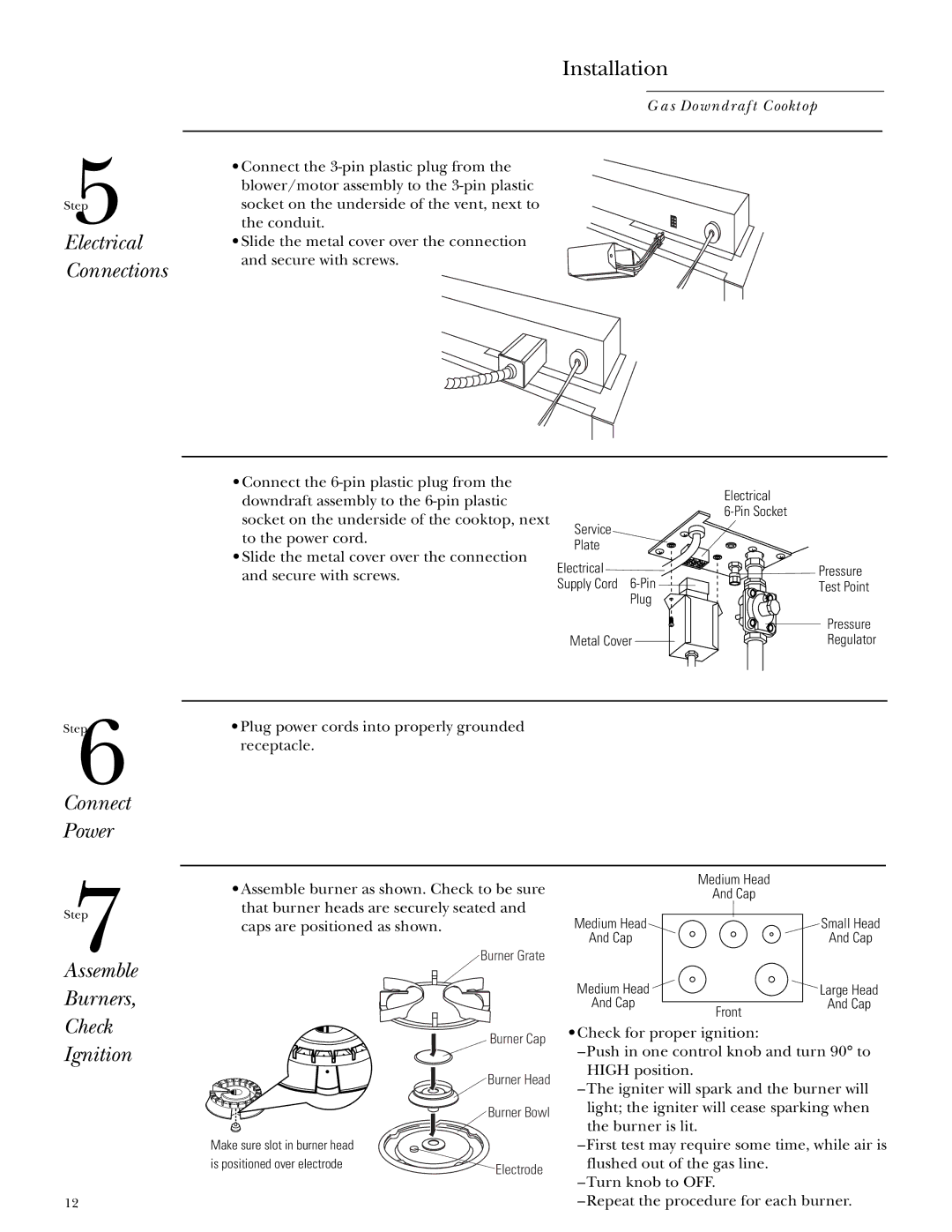
•Connect the
the conduit.
• Slide the metal cover over the connection and secure with screws.
•Connect the
•Slide the metal cover over the connection and secure with screws.
Service
Plate
Electrical
Supply Cord
Plug
Metal Cover
Electrical
Pressure
Test Point
Pressure
Regulator
Step6
Connect
Power
•Plug power cords into properly grounded receptacle.
Step7
Assemble
Burners,
Check
Ignition
12
•Assemble burner as shown. Check to be sure that burner heads are securely seated and caps are positioned as shown.
 Burner Grate
Burner Cap
 Burner Head
Burner Bowl
Make sure slot in burner head |
|
is positioned over electrode | Electrode |
|
| Medium Head |
|
| And Cap |
|
Medium Head |
| Small Head |
And Cap |
| And Cap |
Medium Head |
| Large Head |
And Cap | Front | And Cap |
|
|
•Check for proper ignition:
–Push in one control knob and turn 90° to HIGH position.
–The igniter will spark and the burner will light; the igniter will cease sparking when the burner is lit.
–First test may require some time, while air is flushed out of the gas line.
–Turn knob to OFF.
–Repeat the procedure for each burner.
