Manuals
/
Generac
/
Lawn and Garden
/
Portable Generator
Generac
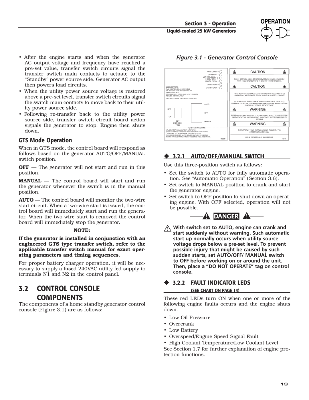
005031-2 3.2CONTROL CONSOLE COMPONENTS, GTS Mode Operation, 3.2.1 AUTO/OFF/MANUAL SWITCH
Models:
005031-2
1
15
56
56
Download
56 pages
18.91 Kb
12
13
14
15
16
17
18
19
Troubleshooting
Specification
Install
‹3.2.2 FAULT INDICATOR LEDS
Warranty
Maintenance
Battery Installation
4.2EXHAUST MANIFOLD PROCEDURE
Air Cleaner
1.2TRANSFER SWITCH
Page 15
Image 15
Page 14
Page 16
Page 15
Image 15
Page 14
Page 16
Contents
This manual should remain with the unit
SHOULD ATTEMPT INSTALLATION
Liquid-cooled,Prepackaged Standby Generators
Model Number 005031-225kW
INTRODUCTION
AUTHORIZED SERVICE DEALER LOCATION
‹OPERATION AND MAINTENANCE
‹HOW TO OBTAIN SERVICE
INTRODUCTION
GENERAL HAZARDS
ELECTRICAL HAZARDS
WARNING
FIRE HAZARDS
EXPLOSION HAZARDS
‹STANDARDS INDEX
1.4GENERATOR AC CONNECTION SYSTEMS
1.2TRANSFER SWITCH
1.1GENERATOR
1.3ATS MODE AUTOMATIC OPERATION
Figure 1.4 - Low Oil Pressure Switch
‹1.7.1 LOW OIL PRESSURE SWITCH
‹1.7.2 HIGH COOLANT TEMPERATURE SWITCH
‹1.7.3 LOW COOLANT LEVEL SWITCH
1.8UNPACKING
1.10 SPECIFICATIONS
‹1.7.6 LOW BATTERY
‹1.8.1 UNPACKING PRECAUTIONS
1.13 ENGINE OIL RECOMMENDATIONS
1.12RECONFIGURING THE FUEL SYSTEM FOR LP VAPOR
Figure 1.8 - Reconfigure the Fuel System
1.11 FUEL CONSUMPTION
‹2.1.1 NFPA STANDARDS
2.1STANDBY GENERATOR INSTALLATION
1.15 BEFORE INSTALLATION
1.14 COOLANT RECOMMENDATIONS
‹2.1.2 OTHER PUBLISHED STANDARDS
2.2GENERATOR LOCATION
2.3GENERATOR MOUNTING AND SUPPORT
2.4BASIC STANDBY ELECTRIC SYSTEM
2.7GROUNDING THE GENERATOR
2.9USING A “GTS” TRANSFER SWITCH
2.5EMERGENCY CIRCUIT ISOLATION METHOD
2.6TOTAL CIRCUIT ISOLATION METHOD
2.10 BATTERY INSTALLATION
Pos2 OFF — ATS Application
‹2.10.1 VENTED BATTERIES
‹2.11.4 GENERATOR SET LUBRICATION
3.1GTS TRANSFER SWITCH
‹2.11.2 TRANSFER SWITCH
2.11 PREPARATION BEFORE START-UP
GTS Mode Operation
‹3.2.1 AUTO/OFF/MANUAL SWITCH
‹3.2.2 FAULT INDICATOR LEDS
3.2CONTROL CONSOLE COMPONENTS
‹3.2.6 SYSTEM READY LED
‹3.2.5 SET EXERCISE TIME SWITCH
‹3.2.3 15 AMP FUSE
‹3.2.4 5 AMP FUSE
Figure 3.2 - Engine Governor Adjustment
3.4ENGINE GOVERNOR GAIN ADJUSTMENTS
3.3MANUAL TRANSFER AND START-UP
3.5MANUAL RETRANSFER AND SHUTDOWN
3.7WEEKLY EXERCISE CYCLE
3.8CONTROL BOARD DIP SWITCH SETTINGS
Figure 3.3 - “Set Exercise Time” Switch
3.6AUTOMATIC OPERATION
‹ONCE ANNUALLY
3.9VOLTAGE REGULATOR ADJUSTMENT
‹EVERY THREE MONTHS
‹ONCE EVERY SIX MONTHS
Figure 4.1 - Intake Manifold Installation
4.2EXHAUST MANIFOLD PROCEDURE
4.3INTAKE MANIFOLD PROCEDURE
4.4CYLINDER HEAD PROCEDURE
4.6OVERLOAD PROTECTION FOR
4.8MAINTENANCE OWNER/ OPERATOR CAN PERFORM
‹4.7.2 BATTERY FLUID
‹4.8.2 CHECK BATTERY
‹4.8.8 CHECK FAN BELT
‹4.8.11 CHANGING THE ENGINE AIR CLEANER
Figure 4.4 - Setting the Spark Plug Gap
‹4.8.7 INSPECT EXHAUST SYSTEM
‹4.9.3 BATTERY MAINTENANCE
4.9MISCELLANEOUS MAINTENANCE
‹4.9.1 CLEANING THE GENERATOR
‹4.9.2 BATTERY
Service Maintenance Interval Information
4.10 SCHEDULED MAINTENANCE
Tasks
Level
CORRECTION
TROUBLESHOOTING POINTS
PROBLEM
CAUSE
Section 6 - Electrical Data
Section 6 - Electrical Data
Liquid-cooled25 kW Generators
Section 6 - Electrical Data
Section 6 - Electrical Data
Liquid-cooled25 kW Generators
Section 6 - Electrical Data
Section 6 - Electrical Data
Liquid-cooled25 kW Generators
Section 6 - Electrical Data
Section 6 - Electrical Data
Section 7 - Exploded Views and Parts Lists
Mounting Base - Drawing No. 0F0104-B
DESCRIPTION
38 3 45 39 32 18 LATCH DETAIL
Enclosure - Drawing No. 0F1645-H
Liquid-cooled25 kW Generators
0F0790
Control Panel 25kW - Drawing No. 0E7615-C
0F0790
RADIATOR
FOR HARNESS GROUND
STEPPER
ONLY
Engine - Drawing No. 0E9918-F
COVER
Fuel System - Drawing No. 0E9980-D
LEADS
LOCKTIGHT
0F1659A
Muffler - Drawing No. 0F2930-C
Stepper Motor - Drawing No. 0E9979-C
Radiator - Drawing No. 0E9965-F
TO THERMOSTAT
ADAPTER
Section 8 - Installation Diagram
YOUR WARRANTY RIGHTS AND OBLIGATIONS
PURCHASER’S/OWNER’S WARRANTY RESPONSIBILITIES
CALIFORNIA EMISSION CONTROL WARRANTY STATEMENT
EMISSION RELATED PARTS INCLUDE THE FOLLOWING
EMISSION CONTROL SYSTEM WARRANTY
THIS WARRANTY SHALL NOT APPLY TO THE FOLLOWING
WARRANTY SCHEDULE
Top
Page
Image
Contents