SETUP AND CONNECTIONS
•Ensure that the power switch of this unit (and of other equipment to be connected) is set to “Off” before commencing connection.
•Do not block the ventilation holes of any of the equipment and arrange them so that air can circulate freely.
•Read through the instructions before connecting other equipment.
•Ensure that you observe the
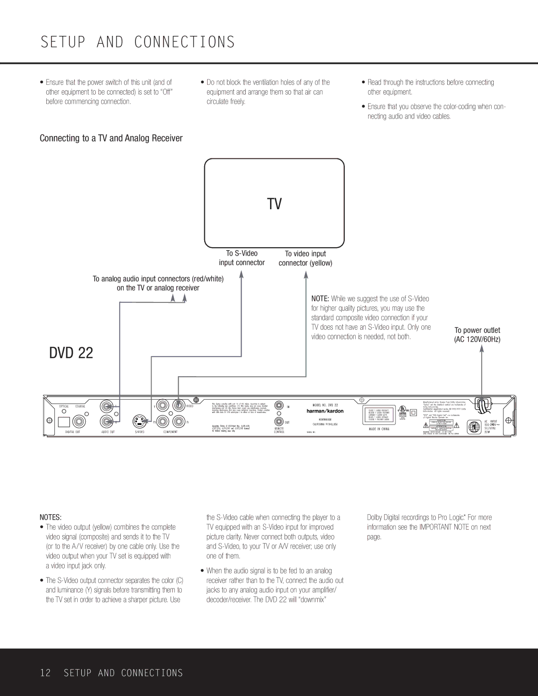
Connecting to a TV and Analog Receiver
TV
To
input connector
To analog audio input connectors (red/white)
on the TV or analog receiver
DVD 22
To video input
connector (yellow)
NOTE: While we suggest the use of
To power outlet (AC 120V/60Hz)
240 ![]()
![]()
NOTES:
•The video output (yellow) combines the complete video signal (composite) and sends it to the TV (or to the A/V receiver) by one cable only. Use the video output when your TV set is equipped with
a video input jack only.
•The
the
•When the audio signal is to be fed to an analog receiver rather than to the TV, connect the audio out jacks to any analog audio input on your amplifier/ decoder/receiver. The DVD 22 will “downmix”
Dolby Digital recordings to Pro Logic.* For more information see the IMPORTANT NOTE on next page.
12 SETUP AND CONNECTIONS
