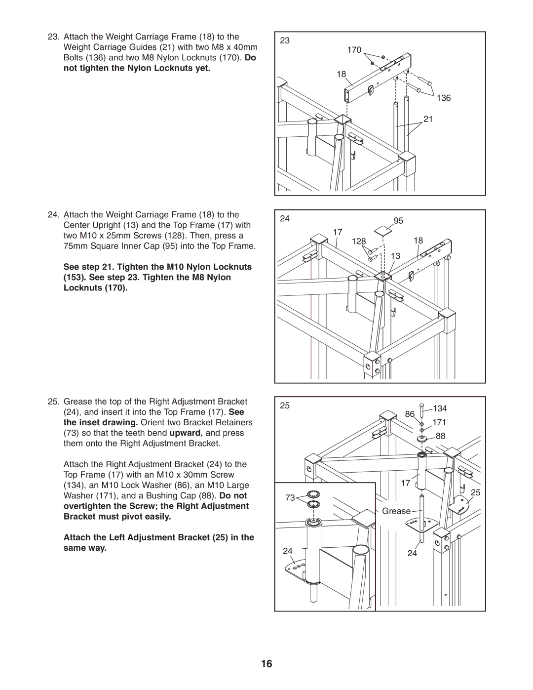
23. Attach the Weight Carriage Frame (18) to the | 23 |
| |
Weight Carriage Guides (21) with two M8 x 40mm |
| ||
170 |
| ||
Bolts (136) and two M8 Nylon Locknuts (170). Do |
| ||
|
| ||
not tighten the Nylon Locknuts yet. | 18 |
| |
|
| ||
|
| 136 | |
|
| 21 | |
24. Attach the Weight Carriage Frame (18) to the | 24 | 95 | |
Center Upright (13) and the Top Frame (17) with | |||
17 |
| ||
two M10 x 25mm Screws (128). Then, press a | 18 | ||
128 | |||
75mm Square Inner Cap (95) into the Top Frame. | |||
| 13 | ||
|
|
See step 21. Tighten the M10 Nylon Locknuts (153). See step 23. Tighten the M8 Nylon Locknuts (170).
25. Grease the top of the Right Adjustment Bracket | 25 | 134 | |
(24), and insert it into the Top Frame (17). See | |||
| 86 | ||
the inset drawing. Orient two Bracket Retainers |
| 171 | |
(73) so that the teeth bend upward, and press |
| 88 | |
them onto the Right Adjustment Bracket. |
| ||
|
| ||
Attach the Right Adjustment Bracket (24) to the |
|
| |
Top Frame (17) with an M10 x 30mm Screw |
| 17 | |
(134), an M10 Lock Washer (86), an M10 Large |
| ||
Washer (171), and a Bushing Cap (88). Do not | 73 | 25 | |
| |||
overtighten the Screw; the Right Adjustment |
| Grease | |
Bracket must pivot easily. |
| ||
|
| ||
Attach the Left Adjustment Bracket (25) in the |
|
| |
same way. | 24 | 24 | |
| |||
| 16 |
|