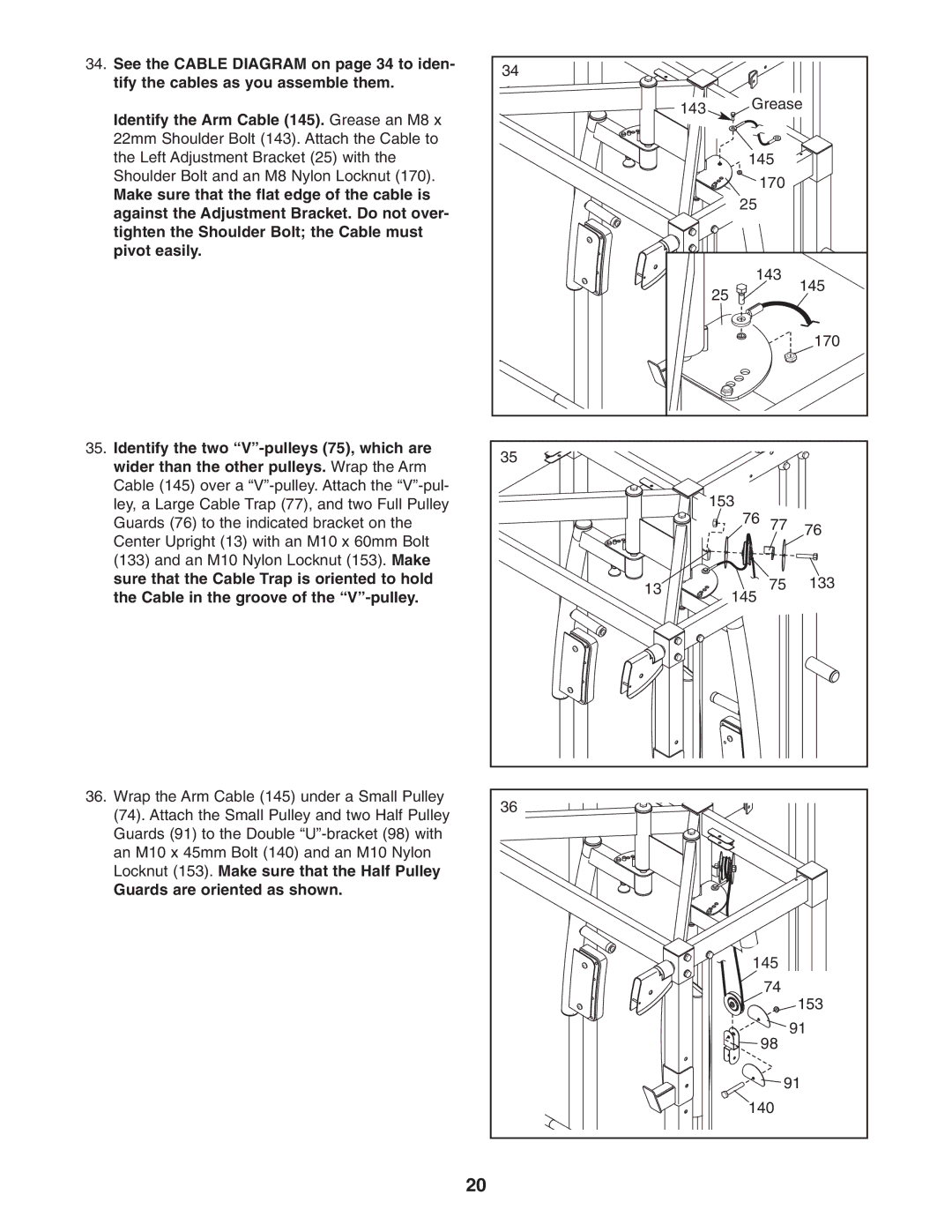
34. See the CABLE DIAGRAM on page 34 to iden- | 34 |
|
|
|
tify the cables as you assemble them. |
|
|
| |
|
|
|
| |
Identify the Arm Cable (145). Grease an M8 x |
| 143 | Grease | |
|
|
| ||
|
|
|
| |
22mm Shoulder Bolt (143). Attach the Cable to |
|
|
|
|
the Left Adjustment Bracket (25) with the |
|
| 145 |
|
Shoulder Bolt and an M8 Nylon Locknut (170). |
|
| 170 |
|
Make sure that the flat edge of the cable is |
|
|
| |
|
| 25 |
| |
against the Adjustment Bracket. Do not over- |
|
|
| |
|
|
|
| |
tighten the Shoulder Bolt; the Cable must |
|
|
|
|
pivot easily. |
|
|
|
|
|
|
| 143 | 145 |
|
|
| 25 | |
|
|
|
| |
|
|
|
| 170 |
35. Identify the two | 35 |
|
|
|
wider than the other pulleys. Wrap the Arm |
|
|
| |
|
|
|
| |
Cable (145) over a |
|
| 153 |
|
ley, a Large Cable Trap (77), and two Full Pulley |
|
|
| |
Guards (76) to the indicated bracket on the |
|
| 76 77 | 76 |
Center Upright (13) with an M10 x 60mm Bolt |
|
|
| |
|
|
|
| |
(133) and an M10 Nylon Locknut (153). Make |
|
|
|
|
sure that the Cable Trap is oriented to hold | 13 |
| 75 | 133 |
the Cable in the groove of the |
| |||
|
| 145 |
| |
36. Wrap the Arm Cable (145) under a Small Pulley | 36 |
|
|
|
(74). Attach the Small Pulley and two Half Pulley |
|
|
| |
|
|
|
| |
Guards (91) to the Double |
|
|
|
|
an M10 x 45mm Bolt (140) and an M10 Nylon |
|
|
|
|
Locknut (153). Make sure that the Half Pulley |
|
|
|
|
Guards are oriented as shown. |
|
|
|
|
|
|
| 145 |
|
|
|
| 74 | 153 |
|
|
|
| |
|
|
| 98 | 91 |
|
|
|
| |
|
|
| 91 | |
|
|
| 140 |
|
20
