EVAPORATOR FAN ROTATION CHECK (THREE PHASE MODELS ONLY)

Check that fan rotates clockwise when viewed from the drive side of unit and in accordance with rotation arrow shown on blower housing. If it does not, reverse any two incoming power cables at Single Point Power Block. In this case, repeat bear- ing check.

Do not attempt to change load side wiring. Internal wiring assures all motors and compressors will rotate in correct di- rection once evaporator fan motor rotation check has been made.

ELECTRICAL INPUT CHECK

Make preliminary check of evaporator fan ampere draw and verify that motor nameplate amps are not exceeded. A final check of amp draw should be made upon completion of air balancing of the duct system (see Appendix C).

RESTORING CONNECTIONS

With disconnect switch open, remove jumper wire from ter- minals R and G at TB1 terminal block, and reconnect ther- mostat wires to terminals Y and W.

REFRIGERATION SYSTEM CHECKS

Ensure the hold-down bolts on the compressor are secure and have not vibrated loose during shipment. Check that vi- bration grommets have been installed. Visually check all pip- ing and clamps. The entire refrigeration system has been factory charged and tested, making it unnecessary to field charge. Factory charges are shown in Appendix C and on the unit nameplate.

Install service manifold hoses. Gauges should read satura- tion pressure corresponding to ambient temperature. Charge should be checked to obtain 12° to 15° of sub-cooling per system (i.e. compressor circuits).

Rollout Protection Control

If the power to the unit is interrupted during the heating cycle, it may cause the secondary limit to trip. Once the blower com- partment temperature drops below the limit reset tempera- ture, the limit will automatically reset. The unit will restart after one (1) hour.

Pre-Operation Checks

1.Close the manual gas valve external to the unit.

2.Turn off the electrical power supply to the unit.

3.Set the room thermostat to its lowest possible setting.

4.Remove the heat exchanger door on the side of the unit by removing screws.

5.This unit is equipped with an ignition device which automatically lights the main burner. DO NOT try to light burner by any other method.

6.Move the gas control valve switch to the OFF position. Do not force.

7.Wait five minutes to clear out any gas.

8.Smell for gas, including near the ground. This is important because some types of gas are heavier than air. If you have waited five minutes and you do smell gas, immediately follow the warnings on page 3 of this manual. If having waited for five minutes and no gas smell is noted, move the gas control valve switch to the ON position.

9.Replace the heat exchanger door on the side of the unit.

10.Open the manual gas valve external to the unit.

11.Turn on the electrical power supply to the unit.

12.Set the thermostat to desired setting.

Gas Supply And Manifold Check

Gas supply pressure and manifold pressure with the burners operating must be as specified on the rating plate.

Gas Inlet Pressure Check

Gas inlet pressure must be checked and adjusted in accor- dance to the type of fuel being consumed.

With Power And Gas Off:

The rollout protection device opens, cutting power to the gas valve, if the flames from the burners are not properly drawn into the heat exchanger. The rollout protection device is located on the burner bracket. The reason for elevated temperatures at the control should be determined and repaired prior to resetting this manual reset control.

WARNING

TO AVOID PROPERTY DAMAGE, PERSONAL INJURY OR DEATH DUE TO FIRE OR EXPLOSION, A QUALIFIED SERVICER MUST INVESTIGATE THE REASON FOR THE ROLLOUT PROTECTION DEVICE TO OPEN BEFORE MANUALLY RESETTING THE ROLLOUT PROTECTION DEVICE.

1.Connect a water manometer or adequate gauge to the inlet pressure tap of the gas valve.

Inlet gas pressure can also be measured by removing the cap from the dripleg and installing a predrilled cap with a hose fitting.

With Power And Gas On:

2.Put unit into heating cycle and turn on all other gas consuming appliances.

INLET GAS PRESSURE

NATURAL Min. 5.0" W.C., Max. 10.0" W.C.

PROPANE Min. 11.0" W.C., Max. 14.0" W.C.

Secondary Limit Control

The secondary limit control is located on the top of the blower scroll assembly. This control opens when elevated tempera- tures are sensed. Elevated temperatures at the control are normally caused by blower failure. The reason for the open- ing should be determined and repaired prior to resetting.

16

NOTE: Inlet Gas Pressure Must Not Exceed the Maximum Value Shown.

If operating pressures differ from above, make necessary pressure regulator adjustments, check piping size, etc., and/ or consult with local utility.

Page 16
Image 16
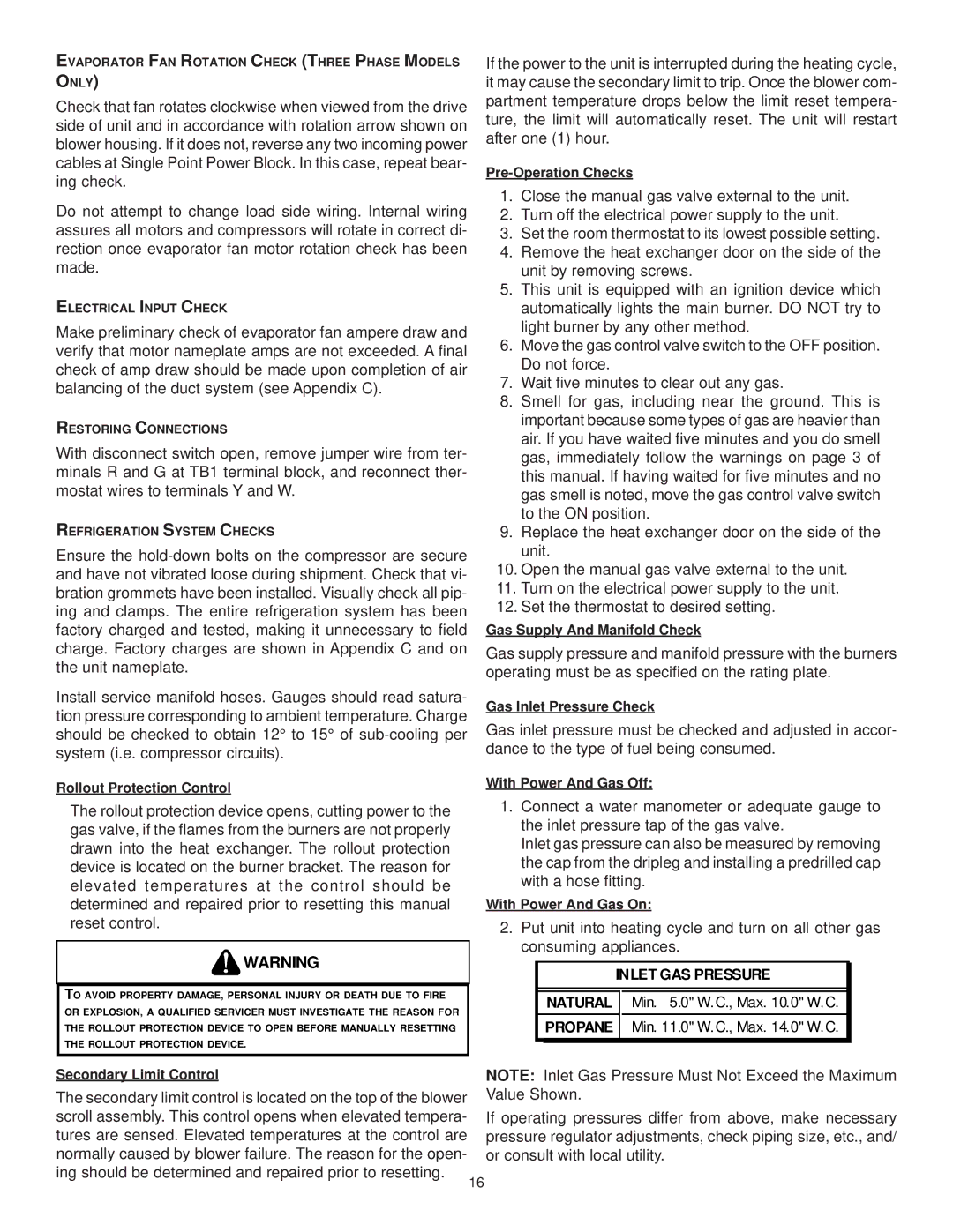
Goodman Mfg CPG SERIES installation manual Rollout Protection Control

CPG SERIES specifications

Goodman Manufacturing has long been a trusted name in the HVAC industry, known for delivering reliable and efficient heating and cooling solutions. Among its impressive lineup is the CPG series, a collection of packaged units that cater to a wide range of residential and commercial applications. The CPG series is designed with the latest technologies and features, making it an ideal choice for those seeking comfort and performance.

One of the most significant characteristics of the CPG series is its energy efficiency. Engineered to meet rigorous energy standards, these units utilize advanced refrigerant technologies that not only lower energy consumption but also contribute to reducing environmental impact. The high-efficiency scroll compressor within the CPG series is designed to operate quietly and smoothly, ensuring that homeowners enjoy a comfortable indoor environment without disruptive noise.

The CPG series also stands out with its robust construction. Each unit is crafted from durable materials that can withstand various weather conditions, ensuring longevity and reliability. The all-aluminum evaporator coil enhances corrosion resistance, prolonging the unit's lifespan and maintaining optimal performance throughout its operation.

In terms of features, the CPG series offers an integrated microprocessor control system that optimizes performance based on real-time environmental data. This smart technology allows for accurate temperature control and improved efficiency by adapting to changing conditions. Furthermore, the series provides multiple capacity options, making it flexible for various building sizes and requirements.

Ease of installation and maintenance is another hallmark of the CPG series. These packaged units are designed for quick setup, reducing labor costs and installation time. Additionally, the access panels on the units are strategically placed, facilitating easier maintenance and servicing. This advantage not only enhances user convenience but also ensures that the units operate efficiently for years to come.

Moreover, the CPG series supports various accessories and enhancements, such as advanced filtration systems and programmable thermostats, allowing users to customize their HVAC system based on specific needs and preferences.

In conclusion, the Goodman CPG series embodies a perfect blend of efficiency, durability, and technology. With its focus on energy savings and user-friendly design, it represents a sound investment for those seeking superior HVAC solutions for their homes or commercial spaces. Whether it's for new construction or an upgrade to an existing system, the CPG series offers performance and reliability that customers can depend on.