313516G
Important Safety Instructions
Automatic AirPro Spray Guns
Instructions-Parts
Orifice Size
Contents
Models
Application
Warnings
FIRE AND EXPLOSION HAZARD
EQUIPMENT MISUSE HAZARD
PRESSURIZED EQUIPMENT HAZARD
TOXIC FLUID OR FUMES HAZARD
PERSONAL PROTECTIVE EQUIPMENT
With Fluid Control Knob for fine adjustment of fluid flow
Selection Charts
General Metal Applications
TERMS
HVLP Guns
High Wear Applications
Wood Applications
Gun Selection
Proper Needle/Nozzle Selection
Air Caps
Conventional Guns
Air Flow
Atomizing Air
Fan Air
Atomizing Air
Fan Air
Maximum HVLP/Compliant inlet manifold pressure
Circulating System
Installation
Ventilate Spray Booth
Configure Gun and Manifold
Ground Spray Gun
Install Air Fittings
Ground Air Compressors and Hydraulic Power Supplies
Ground System
Mount Gun
Reciprocating Arm Rod Mount
Stationary Support
FIG. 5 Retrofit Adapter Plate Mount
Retrofit Adapter Plate
Setup
Connect Air Line
Connect Fluid Hose
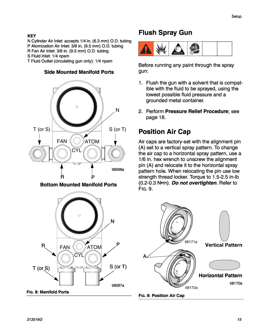
Bottom Mounted Manifold Ports
Flush Spray Gun
Position Air Cap
Side Mounted Manifold Ports
Fan Air psi
Adjust Spray Pattern
Table 1 Suggested Starting Settings
Atomization
NOTE HVLP and Compliant Gun Limits
Incorrect
Pressure Relief Procedure
Operation
Apply Fluid
Daily Gun Care
Clean and Flush Gun
General System Maintenance
Solution
Troubleshooting
General Troubleshooting
Problem
Problem
Spray Pattern Troubleshooting
Problem
Solution
Disassembly
Service
14. Perform the following applicable step
Reassembly
Parts
Parts
ti13593b
† Included in Fluid Seal Repair Kit 24B675 Not sold separately
Included in Air Seal Repair Kit
Size
Repair Kits
General Metal Applications
Orifice
Needle tip and nozzle exit constructed from tungsten carbide
High Wear Applications
Wood Applications
Model has Fluid Control Knob for fine adjustment of fluid flow
Manifold with bottom fluid ports
114101 103 107 105108
Not shown Not sold separately
Part No. 24C342
Not shown, optional size Not sold separately Part No. 288223 only
Part No. 24C342 only
Not shown, optional size Not sold separately Part No. 288217 only
North America Manifold with side fluid ports
International Manifold with side fluid ports
107 101 114 103
3 Torque to 110-130 in-lb 12.3-4.7 Nm
Not shown, optional size Not sold separately Part No. 288160 only
Part No. 288211 only
2 Torque to 8-10 in-lb 0.9-1.3 Nm
Alternate Nozzle Sizes
Accessories
Cleaning Brush
Replacement Gun 24A780
Tips
HVLP Pressure Verification Kit
Inline Fluid Filter 24B707
Spray Tip Filters
Dimensions
Manifold Models 288217 or 288218, All Gun Models
Manifold Model 288221, All Gun Models
Manifold Model 288160 or 288211, All Gun Models
Manifold Model 288223 or 24C342, All Gun Models
Two 0.13 diameter 0.31 in. 7.8 mm holes. Use 1/8 in. pin
Mounting Hole Layouts
Manifold Models 288217 or 288218, All Gun Models
Two M5 x 0.8 x 0.25 in. 6.3 mm holes
for alignment
Manifold Model 288221, All Gun Models
Two M5 x 0.8 x 0.25 in. 6.3 mm holes
Two 0.13 diameter 0.31 in. 7.8 mm holes. Use 1/8 in. pin
Four M6 x 1.0 x 0.34 in
Manifold Model 288223 or 24C342, All Gun Models
6.3 mm holes
Mounting Hole Layouts
for alignment
Manifold Model 288160 or 288211, All Gun Models
Two M5 x 0.8 x 0.25 in. 6.3 mm holes
Two 0.13 diameter 0.31 in. 7.8 mm holes. Use 1/8 in. pin
ti8178a
Retrofit Adapter Plate
2.3 in 57.7 mm
Mounting Hole Layouts
Cylinder Air
Technical Data
Triggering Speed
Sound Data
Graco Information
Graco Standard Warranty