16.Remove the control panel and set it to the side without disconnecting any wiring.
17.Loosen the strain relief on the conveyor motor cord, and disconnect wiring inside the conveyor motor junction box.
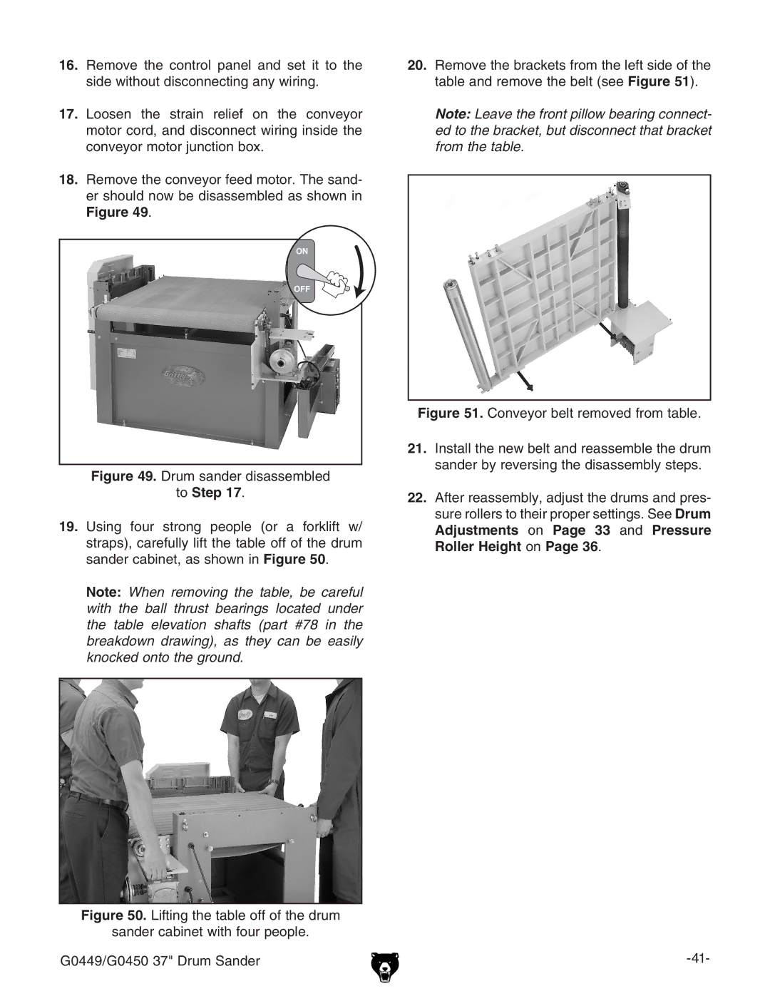
18.Remove the conveyor feed motor. The sand- er should now be disassembled as shown in Figure 49.
Figure 49. Drum sander disassembled
to Step 17.
19.Using four strong people (or a forklift w/ straps), carefully lift the table off of the drum sander cabinet, as shown in Figure 50.
Note: When removing the table, be careful with the ball thrust bearings located under the table elevation shafts (part #78 in the breakdown drawing), as they can be easily knocked onto the ground.
Figure 50. Lifting the table off of the drum
sander cabinet with four people.
G0449/G0450 37" Drum Sander
20.Remove the brackets from the left side of the table and remove the belt (see Figure 51).
Note: Leave the front pillow bearing connect- ed to the bracket, but disconnect that bracket from the table.
