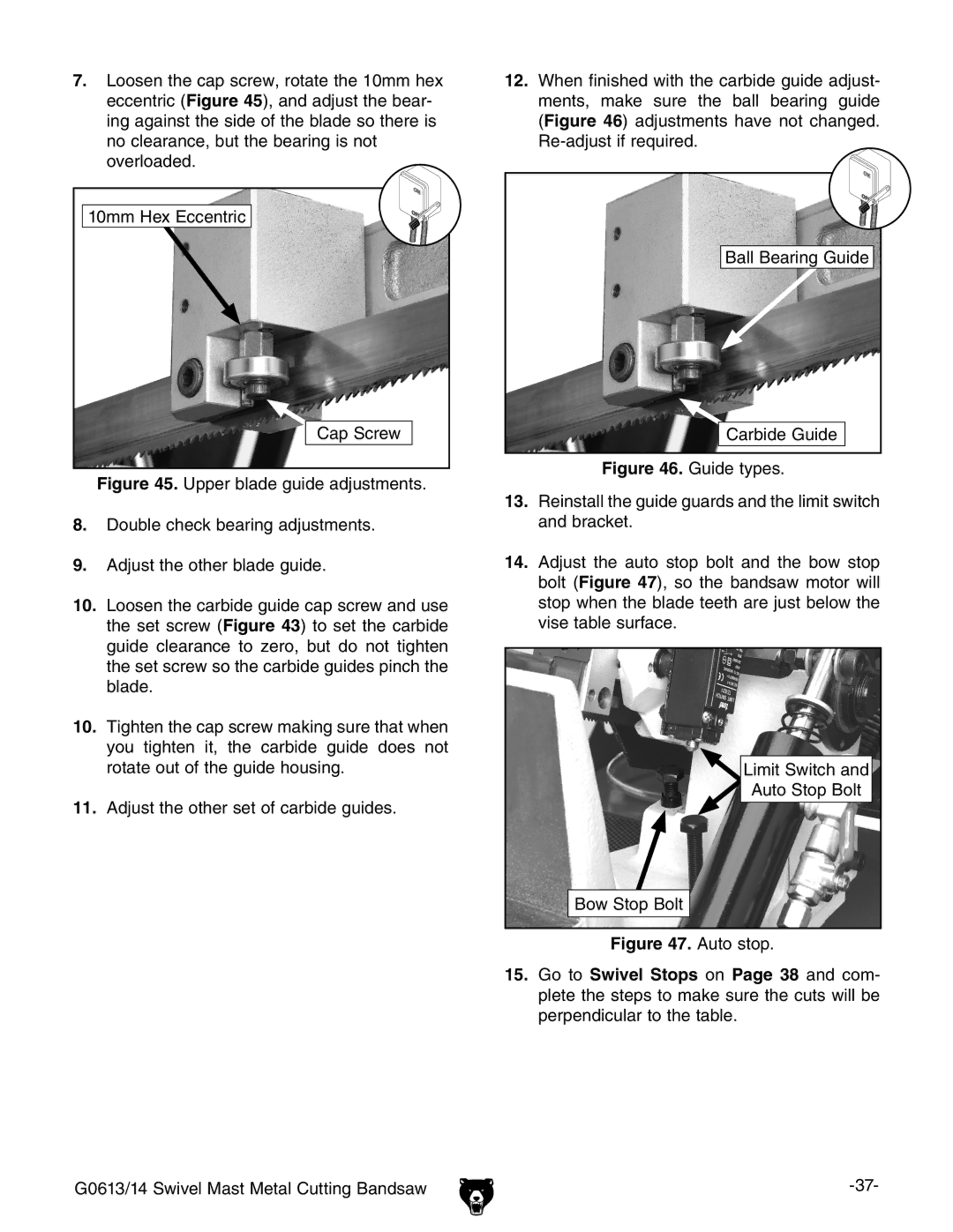
7.Loosen the cap screw, rotate the 10mm hex eccentric (Figure 45), and adjust the bear- ing against the side of the blade so there is no clearance, but the bearing is not overloaded.
10mm Hex Eccentric |
Cap Screw |
Figure 45. Upper blade guide adjustments. |
8.Double check bearing adjustments.
9.Adjust the other blade guide.
10.Loosen the carbide guide cap screw and use the set screw (Figure 43) to set the carbide guide clearance to zero, but do not tighten the set screw so the carbide guides pinch the blade.
10.Tighten the cap screw making sure that when you tighten it, the carbide guide does not rotate out of the guide housing.
11.Adjust the other set of carbide guides.
12.When finished with the carbide guide adjust- ments, make sure the ball bearing guide (Figure 46) adjustments have not changed.
Ball Bearing Guide
Carbide Guide
Figure 46. Guide types.
13.Reinstall the guide guards and the limit switch and bracket.
14.Adjust the auto stop bolt and the bow stop bolt (Figure 47), so the bandsaw motor will stop when the blade teeth are just below the vise table surface.
Limit Switch and |
Auto Stop Bolt |
Bow Stop Bolt |
Figure 47. Auto stop. |
15.Go to Swivel Stops on Page 38 and com- plete the steps to make sure the cuts will be perpendicular to the table.
G0613/14 Swivel Mast Metal Cutting Bandsaw |
