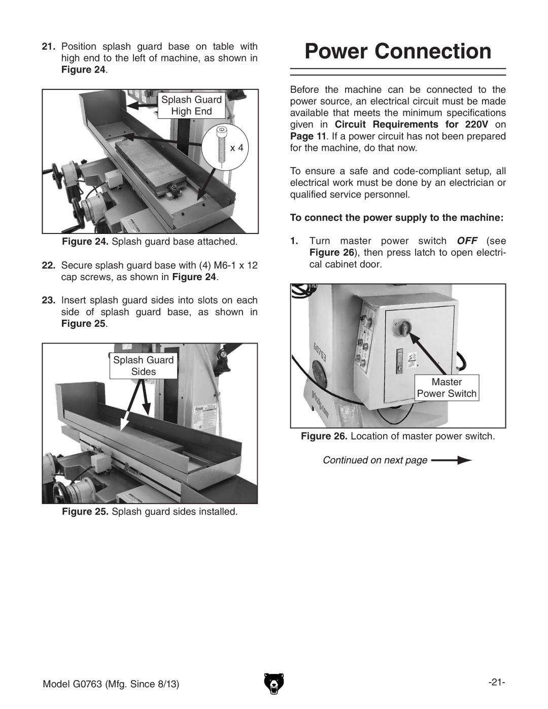
21.Position splash guard base on table with high end to the left of machine, as shown in Figure 24.
Splash Guard
High End
![]() x 4
x 4
Figure 24. Splash guard base attached.
22.Secure splash guard base with (4) M6-1 x 12 cap screws, as shown in Figure 24.
23.Insert splash guard sides into slots on each side of splash guard base, as shown in Figure 25.
Splash Guard
Sides
Figure 25. Splash guard sides installed.
Model G0763 (Mfg. Since 8/13)
Power Connection
Before the machine can be connected to the power source, an electrical circuit must be made available that meets the minimum specifications given in Circuit Requirements for 220V on Page 11. If a power circuit has not been prepared for the machine, do that now.
To ensure a safe and
To connect the power supply to the machine:
1.Turn master power switch OFF (see Figure 26), then press latch to open electri- cal cabinet door.
Master
Power Switch
