Basic Controls
Grinding Wheel & Coolant Controls
Refer to Figures
Additional details for certain controls are also located in the Operations section.
Master Power Switch
A
F
Master
Power Switch
E
B
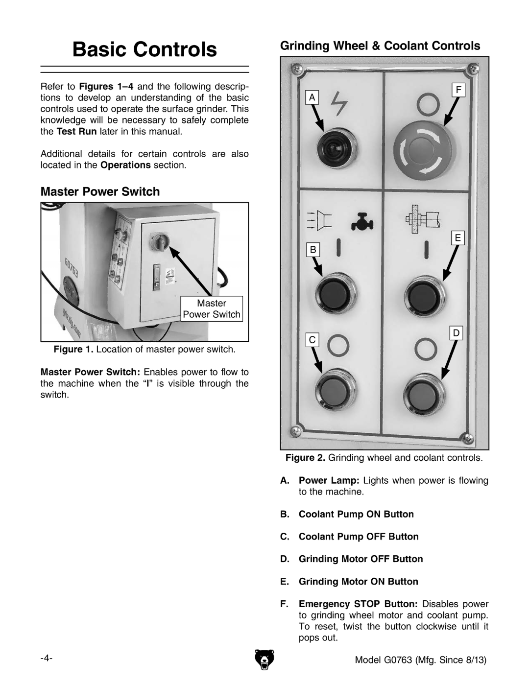
Figure 1. Location of master power switch.
Master Power Switch: Enables power to flow to the machine when the “l” is visible through the switch.
C
D
Figure 2. Grinding wheel and coolant controls.
A. Power Lamp: Lights when power is flowing to the machine.
B. Coolant Pump ON Button
C. Coolant Pump OFF Button
D. Grinding Motor OFF Button
E. Grinding Motor ON Button
F. Emergency STOP Button: Disables power to grinding wheel motor and coolant pump. To reset, twist the button clockwise until it pops out.
Model G0763 (Mfg. Since 8/13) |
