8.Mark a line on wheel at six o'clock position to mark heaviest side of wheel assembly.
9.Center nearest weight with line from above step and secure it in place. This weight will remain in place during following steps.
10.Position remaining two weights evenly around sleeve groove.
11.Place wheel assembly on balancing base. Wheel assembly should not rotate if weights are in correct positions.
12.When you are satisfied with wheel balancing settings, install wheel assembly on machine and test run for 5 minutes to verify balance.
13.To make sure entire width of wheel edge is parallel to table, redress wheel as instructed in Wheel Dressing on Page 31.
Mounting/Removing
Wheel
Before mounting a grinding wheel (new or used), perform the following procedures:
•Wheel Inspection (Page 26)
•Ring Test (Page 26)
•Wheel Balancing (Page 27)
Do not use a wheel that is suspected of having cracks, or if you can see chips, nicks, or dents in the wheel surface. These conditions can lead to wheel failure where the wheel flies apart at oper- ating speed. Always be sure to use a wheel that is rated for operating at speeds of at least 3450 RPM.
Mounting Wheel |
|
Items Needed | Qty |
Grinding Wheel 7" D x 1⁄2" W x 1⁜1⁄4" Bore | 1 |
Wheel Sleeve | 1 |
Wheel Flange | 1 |
Wheel Flange Wrench | 1 |
Arbor Nut | 1 |
Wrench or Socket 19mm | 1 |
To mount wheel assembly:
1.DISCONNECT MACHINE FROM POWER!
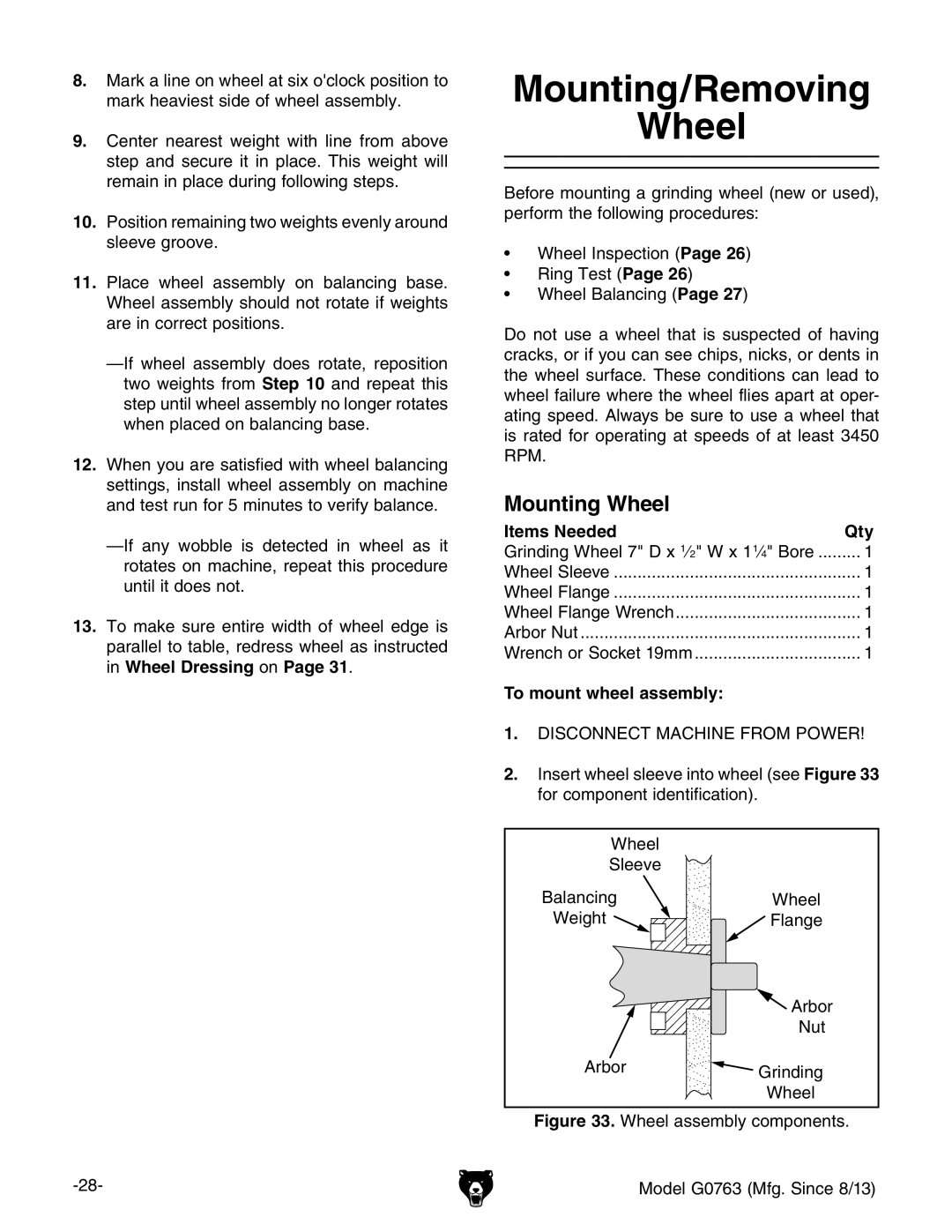
2.Insert wheel sleeve into wheel (see Figure 33 for component identification).
Wheel |
|
Sleeve |
|
Balancing | Wheel |
Weight | Flange |
| Arbor |
| Nut |
Arbor | Grinding |
| |
| Wheel |
