Head Crank
The head crank secures to the left side of the machine and is used to adjust the height of the headstock.
To mount the head crank to the machine:
1.Assemble the head crank by attaching the handle in the same method used for the handwheels. Thread the handle into the crank body, then tighten the lock nut.
2.Slide the head crank onto the shaft, then tighten the set screw to secure it in place (Figure 11).
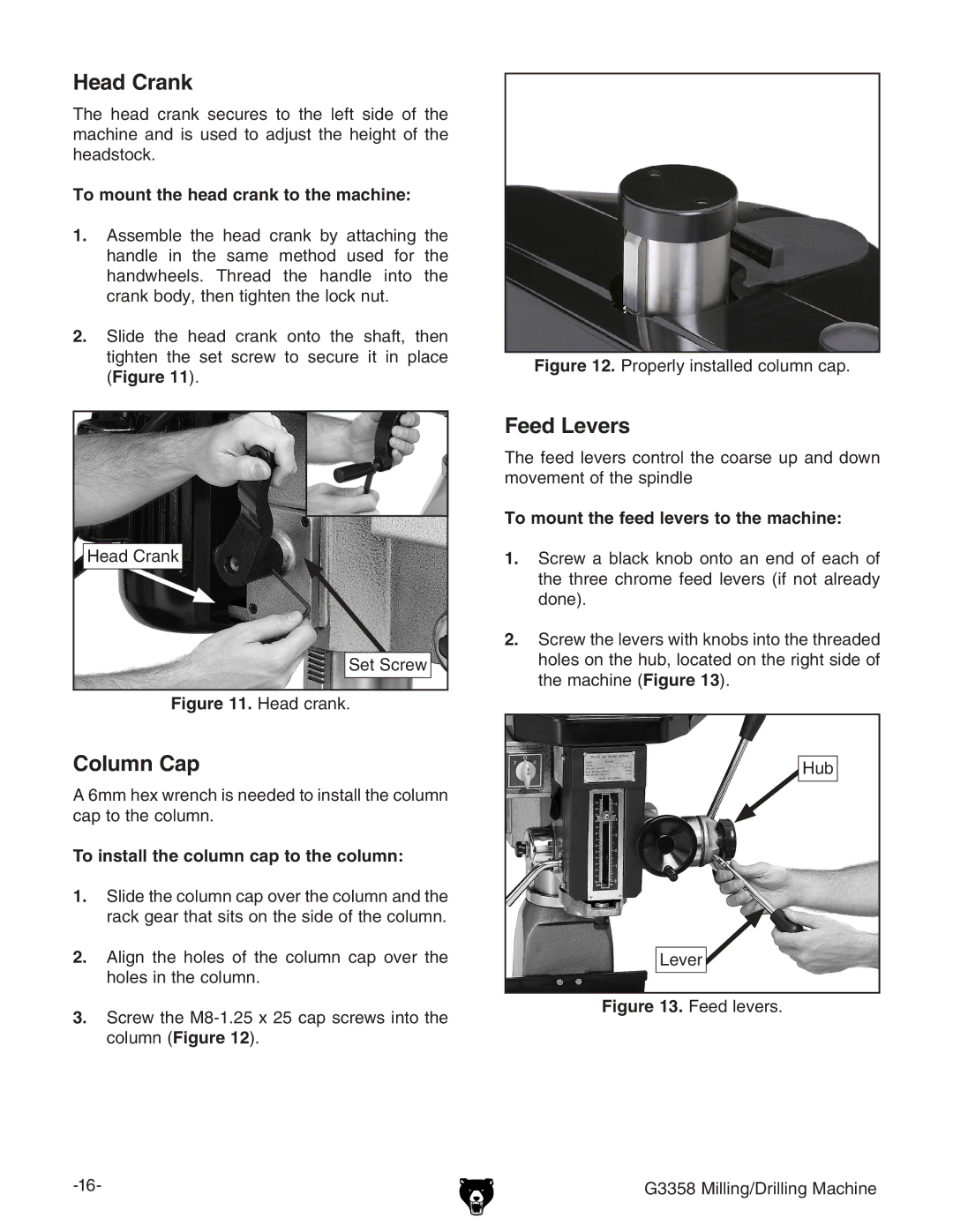
Head Crank
Set Screw
Figure 11. Head crank.
Column Cap
A 6mm hex wrench is needed to install the column cap to the column.
To install the column cap to the column:
1.Slide the column cap over the column and the rack gear that sits on the side of the column.
2.Align the holes of the column cap over the holes in the column.
3.Screw the
Figure 12. Properly installed column cap.
Feed Levers
The feed levers control the coarse up and down movement of the spindle
To mount the feed levers to the machine:
1.Screw a black knob onto an end of each of the three chrome feed levers (if not already done).
2.Screw the levers with knobs into the threaded holes on the hub, located on the right side of the machine (Figure 13).
Hub
Lever![]()