Connecting Accessories
Input Connections
•All control inputs are
•All inputs are connected with respect to COMMON terminal.
•The status LED will blink once when its corresponding input is activated.
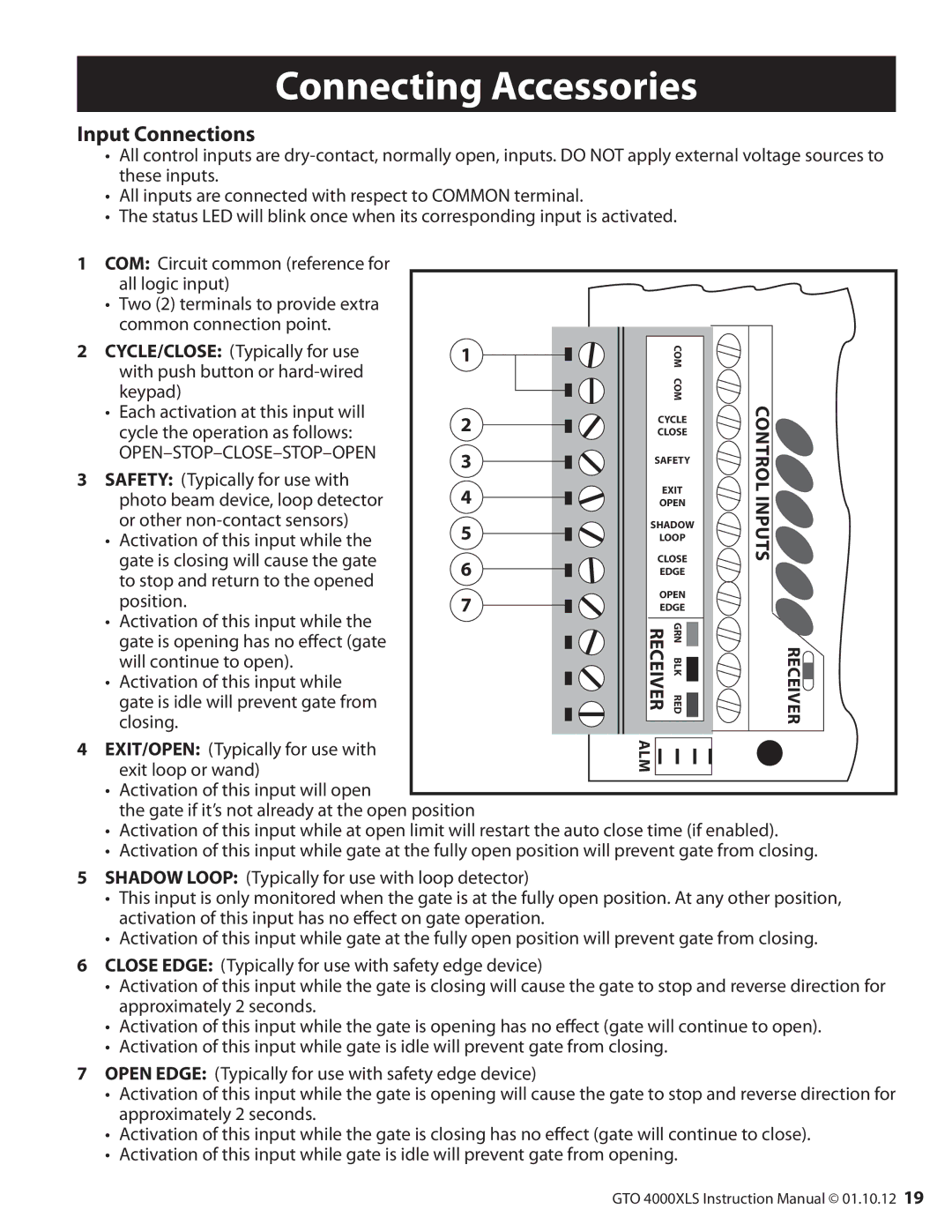
1
COM: Circuit common (reference for all logic input)
•Two (2) terminals to provide extra common connection point.
2
3
CYCLE/CLOSE: (Typically for use with push button or
•Each activation at this input will cycle the operation as follows:
OPEN–STOP–CLOSE–STOP–OPEN
SAFETY: (Typically for use with photo beam device, loop detector or other
•Activation of this input while the gate is closing will cause the gate to stop and return to the opened position.
•Activation of this input while the gate is opening has no effect (gate will continue to open).
•Activation of this input while gate is idle will prevent gate from closing.
1
2
3
4
5
6
7
COM COM
CYCLE
CLOSE
SAFETY
EXIT
OPEN
SHADOW
LOOP
CLOSE
EDGE
OPEN
EDGE
N GR
RECEIVERK
BL
RED
CONTROL INPUTS
RECEIVER![]()
4
5
6
7
EXIT/OPEN: (Typically for use with | ALM | |
exit loop or wand) | ||
|
•Activation of this input will open
the gate if it’s not already at the open position
•Activation of this input while at open limit will restart the auto close time (if enabled).
•Activation of this input while gate at the fully open position will prevent gate from closing.
SHADOW LOOP: (Typically for use with loop detector)
•This input is only monitored when the gate is at the fully open position. At any other position, activation of this input has no effect on gate operation.
•Activation of this input while gate at the fully open position will prevent gate from closing.
CLOSE EDGE: (Typically for use with safety edge device)
•Activation of this input while the gate is closing will cause the gate to stop and reverse direction for approximately 2 seconds.
•Activation of this input while the gate is opening has no effect (gate will continue to open).
•Activation of this input while gate is idle will prevent gate from closing.
OPEN EDGE: (Typically for use with safety edge device)
•Activation of this input while the gate is opening will cause the gate to stop and reverse direction for approximately 2 seconds.
•Activation of this input while the gate is closing has no effect (gate will continue to close).
•Activation of this input while gate is idle will prevent gate from opening.
GTO 4000XLS Instruction Manual © 01.10.12 19