Digital PC sc and RC sc ¾-inch Combination pH/ORP Sensor
USER MANUAL October 2005, Edition
Catalog Number
Page
Table of Contents
Table of Contents
7.3 Troubleshooting the pH or ORP Sensor
Section 8 Replacement Parts and Accessories
8.1 Replacement Items, Accessories, and Reagent and Standards
Section 1 Specifications
Table 1 Combination pH and ORP Sensor Specifications
Table 2 Digital Gateway Specifications
See Figure 1 on page 8 through Figure 4 on page
Page
2.1 Safety Information
2.1.2 Precautionary Labels
Section 2 General Information
2.1.1 Use of Hazard Information
2.2 General Sensor Information
General Information
2.2.1 Sensor Body Styles
Figure 1 Convertible Style Sensor with Flat Electrode
2.4 Operating Precaution
2.3 The Digital Gateway
General Information
Figure 3 Insertion Style Sensor with Domed Electrode
Page
Installation
3.1 Wiring the sc Sensor to the Digital Gateway
Section
DANGER
Installation
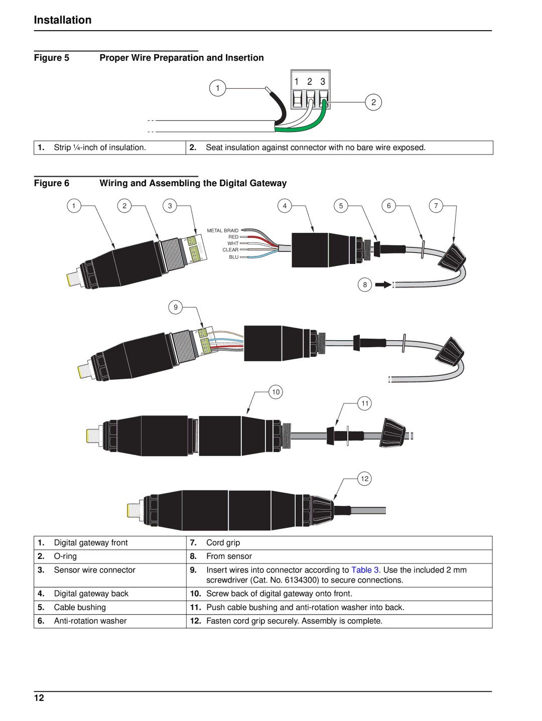
Figure 5 Proper Wire Preparation and Insertion
Figure 6 Wiring and Assembling the Digital Gateway
3.2 Connecting/Wiring the Digital Gateway to the sc100 Controller
Installation
Table 3 Wiring the Digital Gateway Cat. No
DANGER
3.2.1.2 Hard-wiring the Digital Gateway to the sc100
Installation
Installation
Table 4 Wiring the Sensor at Terminal Block J5
Figure 8 Hard-wiring the Digital Gateway
Disconnect Power
3.3 Connecting the Sensor to the sc1000
3.3.1 Connecting the Sensor using the Quick-connect Fittings
Installation
Figure 9 Installing the Connector Safety Lock
3.4 Mounting the Digital Gateway
Installation
Figure 10 Digital Gateway Dimensions
Figure 11 Mounting the Digital Gateway
Page
4.1 Using the sc100 Controller
Section 4 User Interface and Navigation
Table 5 Controller Key Functions/Features
Figure 12 Front of the Controller
User Interface and Navigation 4.1.1 Controller Display Features
4.1.2 Important Key Presses
2 7.00 pH
7.00 pH
4.2 Using the sc1000 Controller
4.2.1 Display Features
4.2.1.1 Using the Pop-up Toolbar
4.2.1.2 Using the Menu Windows
4.2.1.3 Navigating the Menu Windows
User Interface and Navigation
Figure 16 Changing a Menu Item
Keypad
COMMUNICATION ERROR
User Interface and Navigation
List Box
Figure 19 Message window
5.1 Sensor Setup
5.3 Sensor Diagnostics Menu for pH and ORP
5.4 pH Sensor Setup Menu
Section 5 Operation
5.4 pH Sensor Setup Menu continued
Operation
5.5 ORP Sensor Setup Menu
Operation
SELECT SENSOR if more than one sensor is attached
5.6 pH Calibration
5.6.1 One Point Automatic Calibration
5.6.2 Two Point Automatic Calibration
Operation
Operation 5.6.3 One Point Manual Calibration
5.6.4 Two Point Manual Calibration
5.7 ORP Calibration
5.8 Concurrent Calibration of Two Sensors for pH and ORP
5.7.1 One-point Manual Calibration
Operation
5.9 Adjusting the Temperature
Operation
Page
Section 6 Maintenance
6.1 Maintenance Schedule
DANGER
DANGER
6.2 Cleaning the Sensor
Maintenance
Section 7 Troubleshooting
7.1 Error Codes
7.3 Troubleshooting the pH or ORP Sensor
7.2 Warnings
Page
Section 8 Replacement Parts and Accessories
8.1 Replacement Items, Accessories, and Reagent and Standards
Page
Section 9 How to Order
Technical and Customer Service U.S.A. only
U.S.A. Customers
Information Required
Section 10 Repair Service
In the United States
In Canada
In Latin America, the Caribbean, the Far East
Section 11 Limited Warranty
Limitations
Limitation of Remedies
Page
Product Safety
Section 12 Compliance Information
Immunity
Emissions
Canadian Interference-causing Equipment Regulation, IECS-003, Class A
FCC PART 15, Class “A” Limits
Compliance Information
Appendix A Modbus Register Information
Table 8 Sensor Modbus Registers
Modbus Register Information
Table 8 Sensor Modbus Registers
Appendix B General pH Information
B.1 pH Measurement Theory
where
B.2 PID Controller Basics
General pH Information
Phase
Mode
General pH Information
Integral
Derivative
Page
Index